Im looking for a place/person that can do 1UZ wiring for me. My cars an 89 coupe.
If anyone knows of anyone that can and has done the 1UZ wiring before, plz let me know.
Jake
Im looking for a place/person that can do 1UZ wiring for me. My cars an 89 coupe.
If anyone knows of anyone that can and has done the 1UZ wiring before, plz let me know.
Jake
pm corymcarthur this guy knows his wiring dont know if hes has done a 1UZ though
Alright thanks, will do
do it yourself. wiring is easy enough once you find the wiring pinouts.
Im actually not too bad with wiring but this thread just freaks me out
If I can find a simple how to then I will probably do it myself.
+1 for cory. Busy guy, but good at what he does. Has helped me and a number of friends out in the past.
Holy crap! I see what you mean about needing help!
I think there are companies that will do the harness for you on the net. I saw a couple, but can’t remember where I saw them. Do a search.
Edit: wiringspecialties.com Plug and play harnesses
Thanks
I sent cory a PM.
I emailed wiringspecialties.com and they got back to me within 2 minutes saying they dont do 1UZ… thanks tho
Well if your decent at wiring, get the correct wiring diagrams for both and connect the wires needed to run. If your not connecting the dash or anything it shouldn’t be all that difficult. Realistically you can run the engine on 4 wires.
Its going to be my DD/drift car so I need the dash. If anyone knows of any diagrams let me know
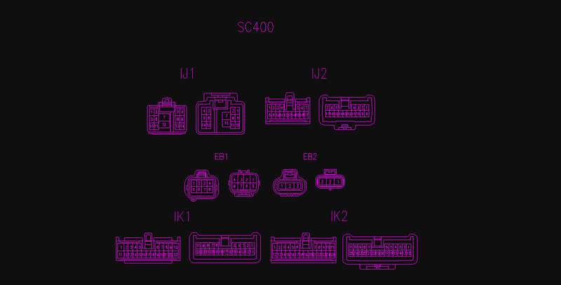
1994 Lexus SC400:
o Pin 1 – Green in color
§ From “FPECU” to “Check Connector”
o Pin 2 – Red-Blue in color
§ From “10A HTR Fuse” to “Water VSV”
o Pin 3 – Empty
§ No Pin? Confirm?
o Pin 4 – White in color
§ From “25A Haz-Horn Fuse” to “Haz Horn”
o Pin 5 – Empty
§ No Pin? Confirm?
o Pin 6 – Black-White in color
§ From “IGN S/W” to “Neutral Safety S/W”
o Pin 7 – Empty
§ No Pin? Confirm?
o Pin 8 – Pink in color
§ From “ECU” to “FPECU”
o Pin 9 – Black-Orange in color
§ From “Haz-Horn” to “Theft ECU”
o Pin 10 – Yellow in color
§ From “10A Gauge Fuse” to “Back Up S/W”
o Pin 11 – Empty
§ No Pin? Confirm?
o Pin 12 – Black-Red in color
§ From “EFI Main Relay” to “FPECU” and “Sub o2 Sensors”
o Pin 13 – White-Black in color
§ From “Trac ECU” to “Ground”
o Pin 14 – Red-Green in color
§ From “ECU” to “FPECU”
o Pin 1 – Red in color
§ From “Cruise CTRL ECU” to “ECU”
o Pin 2 – White-Red in color
§ From “Cruise CTRL ECU” to “ECU”
o Pin 3 – Pink in color
§ From “Comb. Meter” to “ECU”
o Pin 4 – Green-Blue in color
§ From “Cruise CTRL ECU” to “ECU”
o Pin 5 – Empty
§ No Pin? Confirm?
o Pin 6 – Light Green-Black in color
§ From “Progressive Power Steering ECU” to “PPS Solenoid”
o Pin 7 – Green-White in color
§ From “Stop Light S/W” to “ECU”
o Pin 8 – Empty
§ No Pin? Confirm?
o Pin 9 – Brown-Yellow in color
§ From Cruise “CTRL ECU” to “ECU”
o Pin 10 – Empty
§ No Pin? Confirm?
o Pin 11 – Black-Orange in color
§ From “7.5A IGN Fuse” to “ECU”
o Pin 12 – Black-Red in color
§ From “15A ECU-IG Fuse” to “Trac ECU”
o Pin 13 – Empty
§ No Pin? Confirm?
o Pin 14 – Empty
§ No Pin? Confirm?
o Pin 15 – Empty
§ No Pin? Confirm?
o Pin 16 – Light Green-Red in color
§ From “PPS Solenoid” to “PPS ECU”
o Pin 17 – Blue in color
§ From “ECU” to “Kick Down S/W”
o Pin 1 – Brown in color
§ From “Left o2 Sub” to “Ground”
o Pin 2 – Green – Yellow in color
§ From “ECU” to “Data Link Connector 2 (TDCL)”
o Pin 3 – Gray-Yellow in color
§ From “ECU” to “TDCL”
o Pin 4 – Light-Green-Red in color
§ From “ECU” to “TDCL”
o Pin 5 – Green-Red in color
§ From “ECU” to “TDCL”
o Pin 6 – Red in color
§ From “Speed Sensor” to “Comb. Meter”
o Pin 7 – Blue-Red in color
§ From “Speed Sensor” to “Comb. Meter”
o Pin 8 – Black in color
§ From “Igniter” to “Comb. Meter (Tach)”
o Pin 9 – Yellow-Green in color
§ From “Water Temp Sensor” to “Comb. Meter”
o Pin 10 – Pink-Black in color
§ From “Trac ECU” to “TDCL”
o Pin 11 – Black-Red in color
§ From “Back Up Light S/W” to “Back Up Lights”
o Pin 12 – Gray in color
§ From “P S/W” to “Comb. Meter”
o Pin 13 – Blue in color
§ From “N S/W” to “Comb. Meter”
o Pin 14 – Green-White in color
§ From “D S/W” to “Comb. Meter”
o Pin 15 – Empty
§ No Pin? Confirm?
o Pin 16 – Green in color
§ From “2 S/W” to “Comb. Meter”
o Pin 17 – White in color
§ From “1 S/W” to “Comb. Meter”
o Pin 18 – Empty
§ No Pin? Confirm?
o Pin 19 – Empty
§ No Pin? Confirm?
o Pin 20 – Yellow-Black in color
§ “Oil Pressure Sensor” to “Comb. Meter”
o Pin 21 – Green-Orange in color
§ From “ECU” to “Comb. Meter”
o Pin 22 – Gray-Red in color
§ From “ECU” to Comb. Meter”
o Pin 23 – Black-Yellow in color
§ From “Air Back Sensor ECU” to “Check Connector”
o Pin 1 – White in color
§ From “Right o2 Sub” to “ECU”
o Pin 2 – Blue in color
§ From “Short Pin” to “Trac and ABS ECU”
o Pin 3 – Empty
§ No Pin? Confirm?
o Pin 4 – Light Green-Red in color
§ From “TRAC ECU” to “Comb. Meter”
o Pin 5 – White in color
§ From “TRAC ECU” to “Comb. Meter”
o Pin 6 – Empty
§ No Pin? Confirm?
o Pin 7 – Empty
§ No Pin? Confirm?
o Pin 8 – Empty
§ No Pin? Confirm?
o Pin 9 – Blue-Yellow in color
§ From “ECU” to “Comb. Meter (CEL)”
o Pin 10 – Violet-Red in color
§ From “Oil Level S/W” to “Comb. Meter”
o Pin 11 – Empty
§ No Pin? Confirm?
o Pin 12 – Red-Blue in color
§ From “Left o2 Sub” to “ECU”
o Pin 13 – Red-White in color
§ From “P-Brake S/W” to “TRAC ECU”
o Pin 14 – Empty
§ No Pin? Confirm?
o Pin 15 – Red in color
§ From “10A DOME Fuse” to “TRAC ECU”
o Pin 16 – Yellow-Red in color
§ From “TRAC Cut S/W” to “TRAC ECU”
o Pin 17 – Empty
§ No Pin? Confirm?
o Pin 18 – Red-Black in color
§ From “ABS ECU” to “TRAC ECU”
o Pin 19 – Empty
§ No Pin? Confirm?
o Pin 20 – Empty
§ No Pin? Confirm?
o Pin 21 – Empty
§ No Pin? Confirm?
o Pin 22 – Brown-White in color
§ From “Left o2 Sub” to “ECU”
o Pin 23 – Black in color
§ From “Neutral Safety S/W” to “Comb. Meter”
o Pin 24 – Brown-Black in color
§ From “Comb. Meter” to “Ground”
o Pin 25 – Violet in color
§ From “Short Pin” to “ABS ECU”
Engine Bay:
o Pin 1 – Light Blue in color
§ From “A/C Magnetic Clutch Relay” to “A/C Magnetic Clutch”
o Pin 2 – White in color
§ From “A/C Magnetic Clutch Relay" to “ECU”
o Pin 3 – Black in color
§ From “Neutral Safety S/W" to “Starter Relay”
o Pin 4 – Black-Yellow in color
§ From “30A EFU Fuse" to “ECU”
o Pin 5 – Light-Blue in color
§ From “7.5A TRAC Fuse" to “Traction ECU”
o Pin 6 – Black-Red in color
§ From “Short Pin" to “ABS Actuator Relay”
o Pin 7 – Brown in color
§ From “A/C Ambient Temp. Sensor" to “Ground”
o Pin 8 – Black-Orange in color
§ From “ECU" to “EFI Main Relay”
o Pin 1 – Black in color
§ From “Starter Relay” to “Starter”
o Pin 2 – Black-Orange in color
§ From “Ignition Main Relay" to “Ignition System” and “Fuel Injectors”
o Pin 3 – Black-Red in color
§ From “EFI Main Relay” to “ECU (+B & +B1” and “Misc. Equipment (+B)”
1997 Lexus SC400:
Interior:
o Pin 1 – Empty
§ No Pin? Confirm?
o Pin 2 – Red-Light Blue in color
§ From “10A HTR Fuse” to “Water VSV”
o Pin 3 – Black-White in color
§ From “IGN S/W” to “Injectors” and “IGN Coil 2”
o Pin 4 – Light Green in color
§ From “25A Haz-Horn Fuse” to “Haz Horn”
o Pin 5 – Red in color
§ From “Vapor Pressure Sensor” to “ECU”
o Pin 6 – Black-White in color
§ From “7.5A ST Fuse” to “Neutral Safety S/W” and “ECU”
o Pin 7 – Black-White in color
§ From “IGN S/W” to “IGN Coil 1” and “Igniters” and “Injectors”
o Pin 8 – Pink in color
§ From “ECU” to “FPECU”
o Pin 9 – White in color
§ From “Haz-Horn” to “Theft ECU”
o Pin 10 – Yellow in color
§ From “10A Gauge Fuse” to “Back Up S/W”
o Pin 11 – Brown in color
§ From “Vapor Pressure Sensor” to “ECU”
o Pin 12 – Black-Red in color
§ From “EFI Main Relay” to “Sub o2 Sensors”
o Pin 13 – White-Black in color
§ From “Trac ECU” to “Ground”
o Pin 14 – Red-White in color
§ From “ECU” to “FPECU”
o Pin 1 – Red in color
§ From “Cruise CTRL ECU” to “ECU”
o Pin 2 – Red-White in color
§ From “Cruise CTRL ECU” to “ECU”
o Pin 3 – Orange in color
§ From “Comb. Meter” to “ECU”
o Pin 4 – Empty
§ No Pin? Confirm?
o Pin 5 – Light Blue-White in color
§ From “Cooling Fan ECU” to “Solenoid Valve (Cooling Fan)”
o Pin 6 – Light Green in color
§ From “Progressive Power Steering ECU” to “PPS Solenoid”
o Pin 7 – Green-White in color
§ From “Stop Light S/W” to “ECU” and “TRAC ECU”
o Pin 8 – Empty
§ No Pin? Confirm?
o Pin 9 – Brown-Yellow in color
§ From Cruise “CTRL ECU” to “ECU”
o Pin 10 – Empty
§ No Pin? Confirm?
o Pin 11 – Black-Orange in color
§ From “7.5A IGN Fuse” to “ECU”
o Pin 12 – Black-Yellow in color
§ From “15A ECU-IG Fuse” to “Trac ECU”
o Pin 13 – Green in color
§ From “7.5A TAIL Fuse” to “ECU”
o Pin 14 – Red-Black in color
§ From “Cooling Fan ECU” to “Data Link Connector 1”
o Pin 15 – Black in color
§ From “Solenoid Valve (Cooling Fan)” to “Cooling Fan ECU”
o Pin 16 – Yellow in color
§ From “PPS Solenoid” to “PPS ECU”
o Pin 17 – Empty
§ No Pin? Confirm?
o Pin 1 – Brown in color
§ From “Both o2 Sub” to “Ground”
o Pin 2 – Green – Yellow in color
§ From “ECU” to “Data Link Connector 2 (TDCL)”
o Pin 3 – Shielded in color
§ From “Shielded Throttle Driver Wires” to “Throttle Driver”
o Pin 4 – Light Blue in color
§ From “TRAC ECU” to “Throttle Driver”
o Pin 5 – Black-White in color
§ From “TRAC ECU” to “Throttle Driver”
o Pin 6 – Red in color
§ From “Speed Sensor” to “Comb. Meter”
o Pin 7 – Light Blue-Red in color
§ From “Speed Sensor” to “Comb. Meter”
o Pin 8 – Light Green in color
§ From “Igniter” to “Comb. Meter (Tach)”
o Pin 9 – Yellow-Green in color
§ From “Water Temp Sensor” to “Comb. Meter”
o Pin 10 – Yellow in color
§ From “CRU CTRL ECU” to “Data Link Connector 1”
o Pin 11 – Light Blue in color
§ From “Back Up Light S/W” to “Back Up Lights”
o Pin 12 – Black-White in color
§ From “P S/W” to “Comb. Meter”
o Pin 13 – Light Blue-Yellow in color
§ From “N S/W” to “Comb. Meter”
o Pin 14 – Green-Yellow in color
§ From “D S/W” to “Comb. Meter”
o Pin 15 – White-Red in color
§ From “Data Link Connector 3” to “Ground”
o Pin 16 – Green in color
§ From “2 S/W” to “Comb. Meter”
o Pin 17 – White in color
§ From “1 S/W” to “Comb. Meter”
o Pin 18 – Black in color
§ From “ECU” to “Data Link Connector 3”
o Pin 19 – Brown in color
§ From “Shielded Black Pin 18 IK1” to “Ground”
o Pin 20 – Yellow-Black in color
§ “Oil Pressure Sensor” to “Comb. Meter”
o Pin 21 – Green-Orange in color
§ From “ECU” to “Comb. Meter”
o Pin 22 – Gray-Red in color
§ From “ECU” to Comb. Meter”
o Pin 23 – Red-Black in color
§ From “Oil Temp/Oil Level S/W” to “Comb. Meter”
o Pin 1 – Green in color
§ From “Right o2 Sub” to “ECU”
o Pin 2 – Blue in color
§ From “Short Pin” to “Trac and ABS ECU”
o Pin 3 – Empty
§ No Pin? Confirm?
o Pin 4 – Light Green-Red in color
§ From “TRAC ECU” to “Comb. Meter”
o Pin 5 – White in color
§ From “TRAC ECU” to “Comb. Meter”
o Pin 6 – White in color
§ From “ABS SPD Sensor Rear Left” to “TRAC ECU”
o Pin 7 – Light Green in color
§ From “ABS SPD Sensor Rear Right” to “TRAC ECU”
o Pin 8 – Red in color
§ From “Right o2 Sub” to “ECU”
o Pin 9 – Blue-Yellow in color
§ From “ECU” to “Comb. Meter (CEL)”
o Pin 10 – Violet-Red in color
§ From “Oil Level S/W” to “Comb. Meter”
o Pin 11 – Red-White in color
§ From “Brake Fluid Level S/W” to “TRAC ECU”
o Pin 12 – Red-Light Blue in color
§ From “Left o2 Sub” to “ECU”
o Pin 13 – Black-Red in color
§ From “P-Brake S/W” to “TRAC ECU”
o Pin 14 – Empty
§ No Pin? Confirm?
o Pin 15 – Red in color
§ From “10A DOME Fuse” to “TRAC ECU”
o Pin 16 – Yellow-Red in color
§ From “TRAC Cut S/W” to “TRAC ECU”
o Pin 17 – Black in color
§ From “ABS SPD Sensor Rear Left” to “TRAC ECU”
o Pin 18 – White-Red in color
§ From “Shielded ABS SPD Sensor wire” to “Junction Connector”
o Pin 19 – Empty
§ No Pin? Confirm?
o Pin 20 – Empty
§ No Pin? Confirm?
o Pin 21 – Violet in color
§ From “ABS SPD Sensor Rear Right” to “TRAC ECU”
o Pin 22 – Brown-White in color
§ From “Left o2 Sub” to “ECU”
o Pin 23 – Green-Red in color
§ From “Neutral Safety S/W” to “Comb. Meter”
o Pin 24 – White-Black in color
§ From “Comb. Meter” to “Ground”
o Pin 25 – White-Green in color
§ From “Short Pin” to “ABS ECU”
Engine Bay:
o Pin 1 – Light Blue in color
§ From “A/C Magnetic Clutch Relay” to “A/C Magnetic Clutch”
o Pin 2 – White in color
§ From “A/C Magnetic Clutch Relay" to “ECU”
o Pin 3 – Green-Red in color
§ From “Neutral Safety S/W" to “Starter Relay”
o Pin 4 – Black-White in color
§ From “30A EFU Fuse" to “ECU”
o Pin 5 – Light Blue-Red in color
§ From “7.5A TRAC Fuse" to “Traction ECU”
o Pin 6 – Violet in color
§ From “Short Pin" to “ABS Actuator Relay”
o Pin 7 – Brown in color
§ From “A/C Ambient Temp. Sensor" to “Ground”
o Pin 8 – Black-Yellow in color
§ From “ECU" to “EFI Main Relay”
o Pin 1 – Black in color
§ From “Starter Relay” to “Starter”
o Pin 2 – Black-Red in color
§ From “EFI Main Relay" to “AFM (+B & +B1” and “Misc. Equipment (+B)”
o Pin 3 – Black-Red in color
§ From “EFI Main Relay” to “ECU (+B & +B1” and “Misc. Equipment (+B)”
That should help…