LQ9 into E39

^^just because other people are using them without a problem does not mean its right…the parts are meant for a bolt in swap…which in my experience has never been very good. those bolt in mounts i had used were bending on me and the motor did not offset nearly as much as yours will. since my first experience with bolt in mounts, every single swap ive done has been home made/cut/weld mounts.

on the bushing, can you take the stud out and through bolt it so it can be threaded into the mount from the bottom? i assume the bottom of the bushing is just a steel plate that you could knock the stud out of.

I went down to Home Depot on lunch a few days ago and bought (2) 2x6x8’ planks, as well as a 2x2x8’ strip. Cut up the planks into 1’ lengths and doubled them up for 4" tall, 6" wide, 12" long “support spacers” as I like to call them. I also left a few of them loose for when I’m resting the motor on the crossmember for fitment.

I made a huge for sale thread on here and a few other boards, already sold the F Body oil pan, shipping that out today. Bought an LS1 Camaro water pump and starter from one person, a GTO oil pan from another, and ARP Headbolts/assembly lube from Summit Racing. Also grabbed the 6.0 MLS headgaskets from gmpartsdirect. Once I get the heads back on and torqued I can finally mock up the motor since I’ll have the oil pan.

Nothing much to report, just little things I’m getting together.

Sold both my BMW diffs (2.81 and 3.15), both MAFs, the base rails of my roof rack, and the Camaro (rear sump) oil pan.

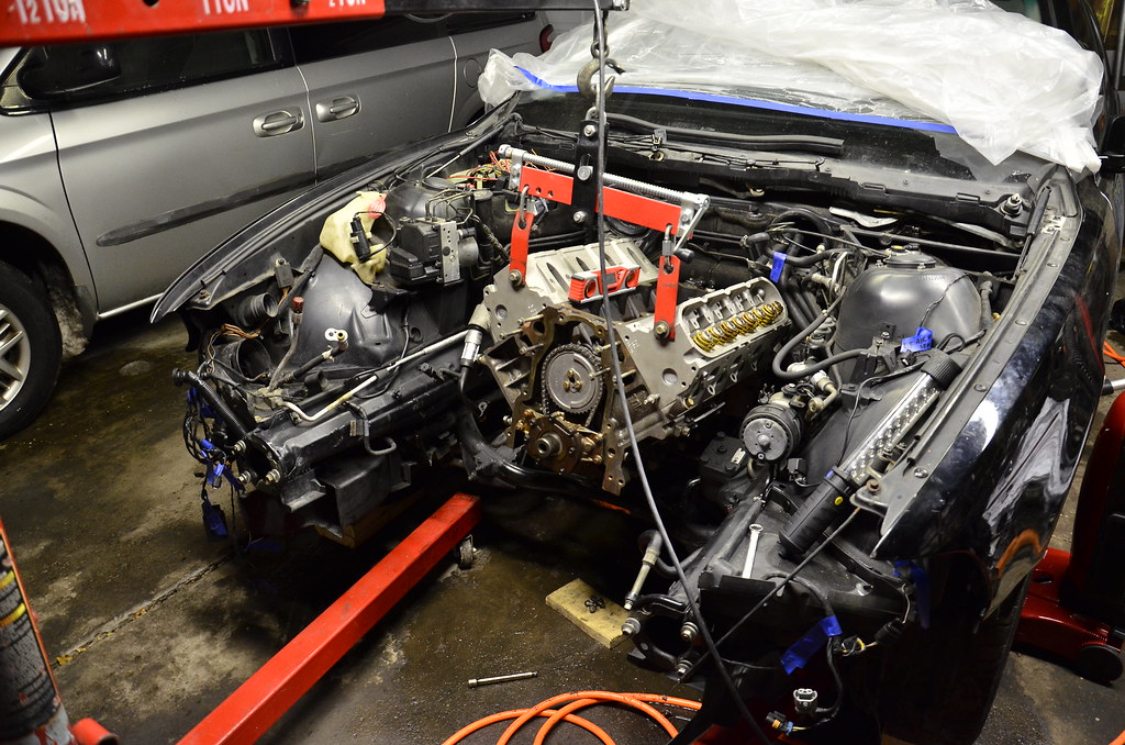
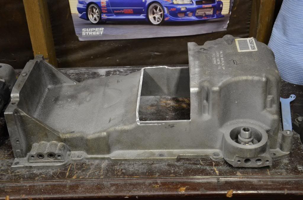
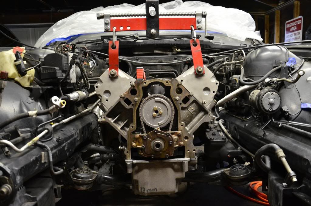
I received my ARP head bolts, GM MLS 6.0 headgaskets, LS1 harmonic balancer, starter, water pump, and GTO oil pan over the last week. The top end of the engine is ready to go back together, but the machine shop lost the dowels in the heads, so I had to special order 3 of those (1 was left in the block). Can’t assemble it until they get in this weekend. Once I do get those I can finally put the heads back on and torque them down, as well as replace both front and rear main seals as well as a ton of other gaskets I bought. At that point I can put the intake manifold on, and it’ll start to look like a real motor (good timing, because I need to know where I’ll have issues for fabbing the motor mounts).

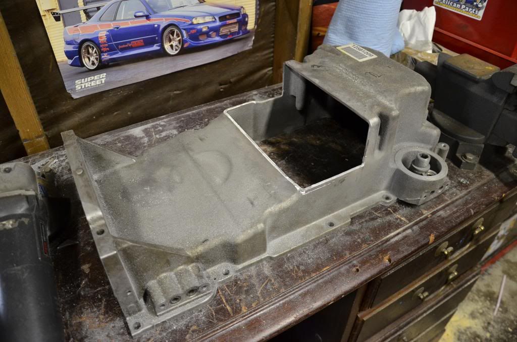
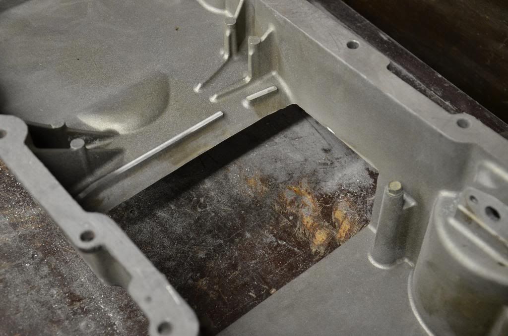
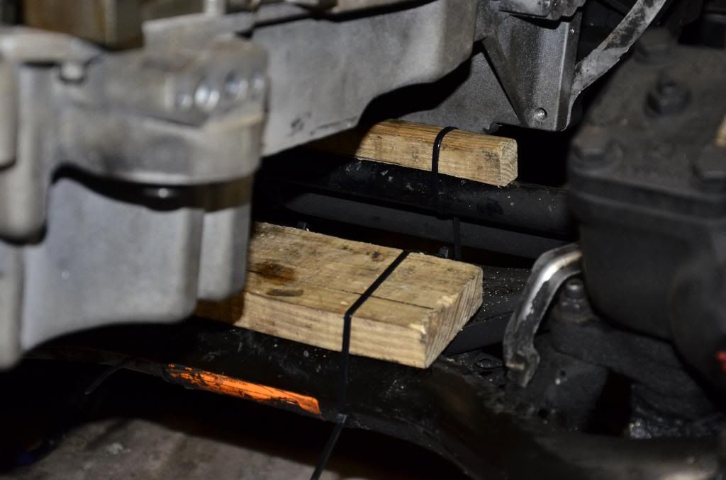
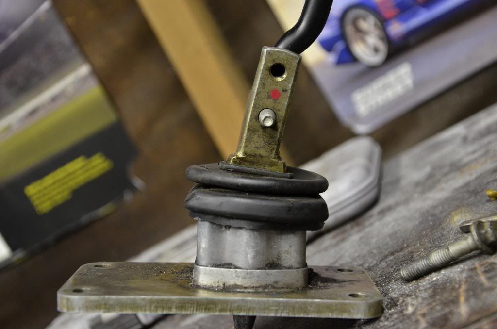
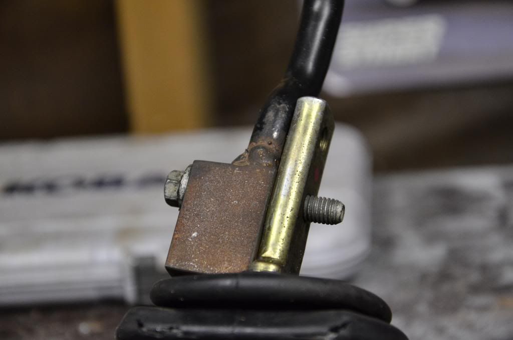
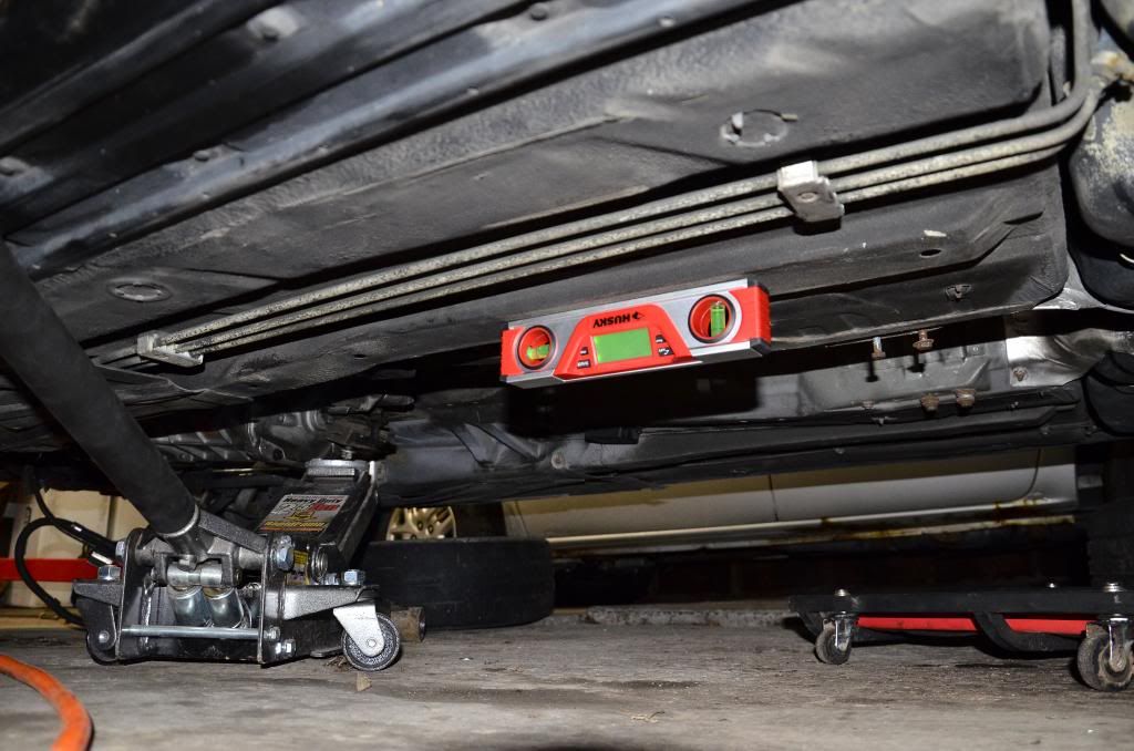
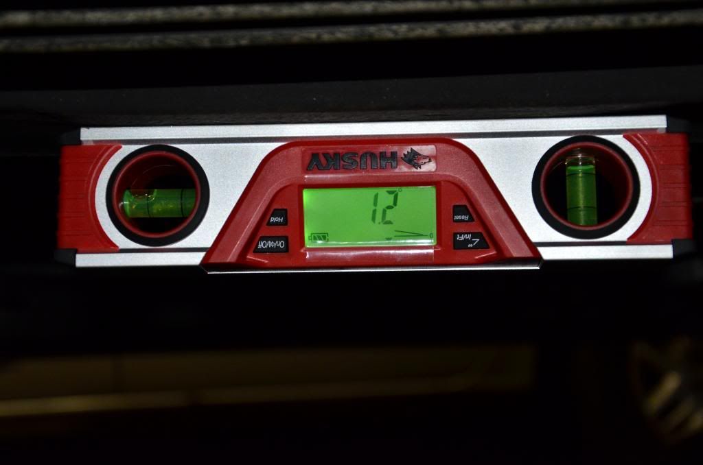
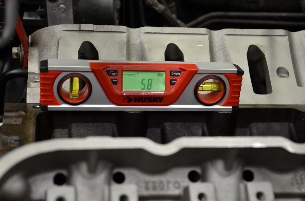
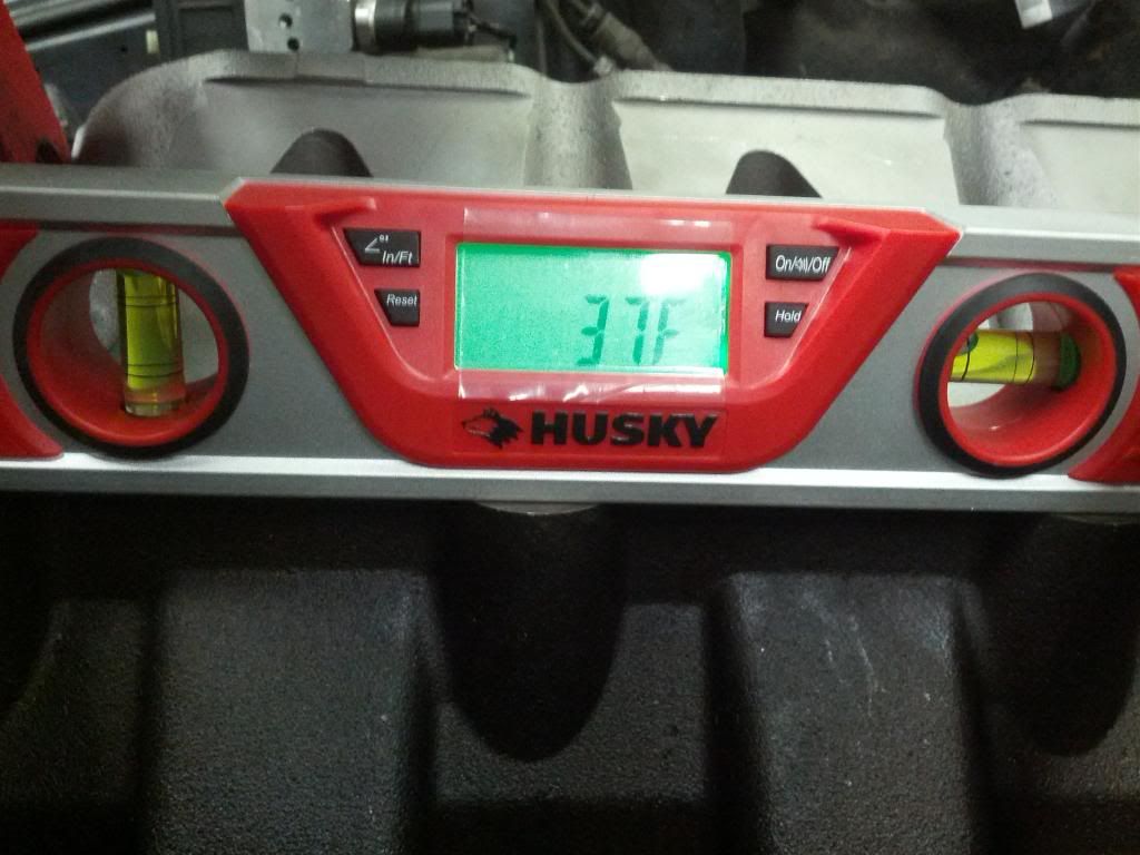
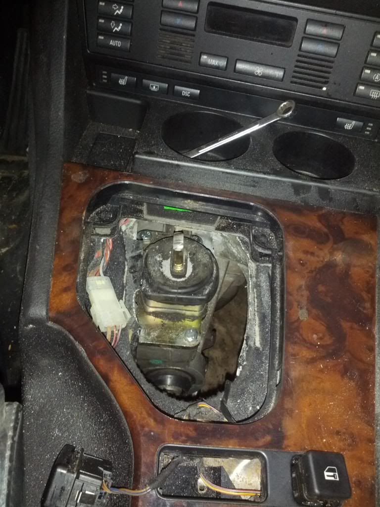
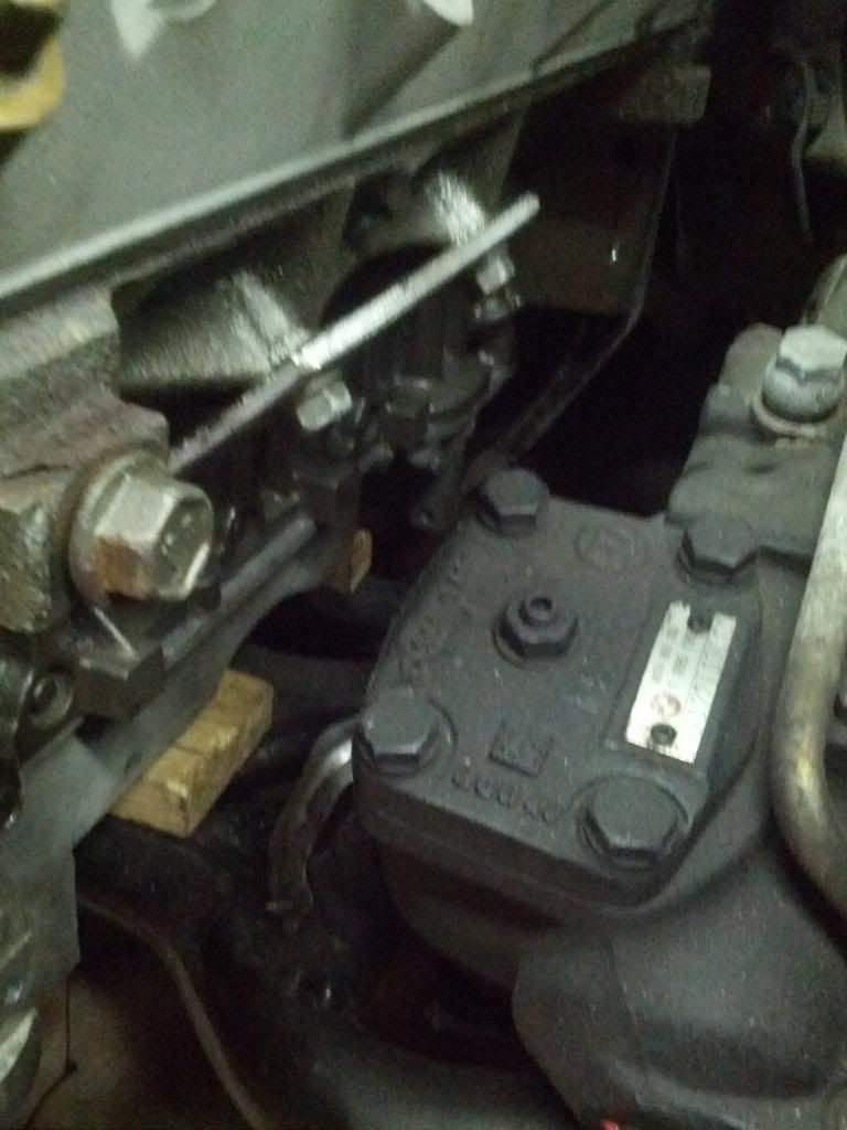
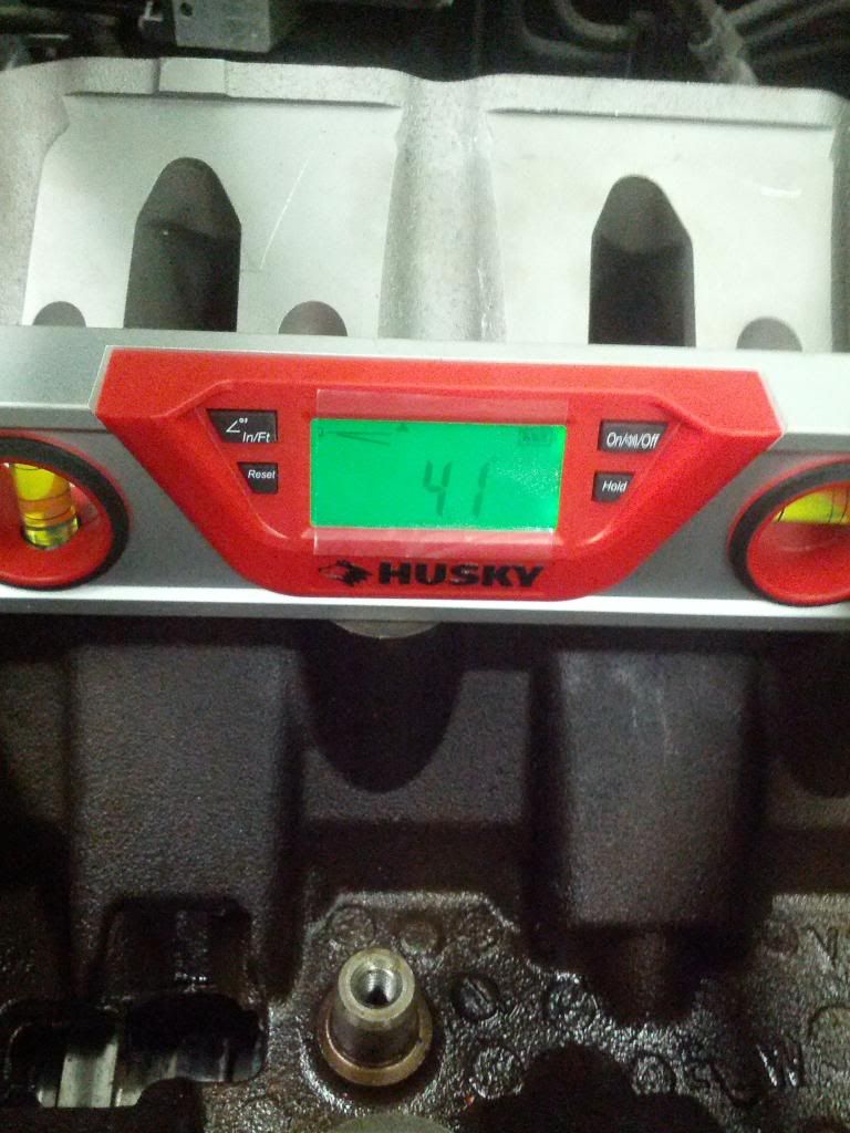
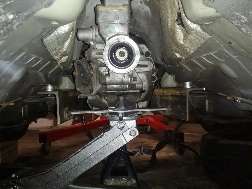
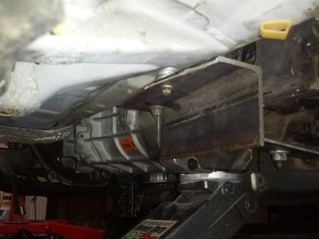
On Saturday, I put the car on some 2x6s I nailed together to raise the car off the ground at all 4 corners. I eyeballed the rough dimensions of the cut on the GTO pan and notched it, test fit, and found that I still need to notch the horizontal portion some more in order for the nose of the motor to come down a few more degrees. With the shifter roughly where it needs to be, the engine is pointing 6* down at the back–I am going for 3*. Having a digital inclinometer accurate to a tenth of a degree is awesome. The motor/pan is resting on a 1" board, so maybe it’s a bit overkill as far as spacing from the crossmember, but I am assuming the new stock rubber engine mounts will squish down some when the weight of the drivetrain comes down onto them.

My right angle grinder backing plate fell apart, and Home Depot was already closed, so I wasn’t able to finish trimming the pan. Today on lunch I went to the store and picked up the proper backing plate/ring along with an 11/32" drill bit, which I’ll need to drill out the boss on the block for the alternator to mount to. I have the LQ4 truck alternator as it came with my motor, but is it the same type as the LS1 style? It looks like any old small car-style alternator. I’ll have to see if there’s a part number on it and cross reference to see if I can reuse it. I’m still on the hunt for a cheap OEM LS1 alternator bracket.

Buying a used LS1 power steering pump was ehhhhhhhhh, so I found a nice cheap one on Rockauto and grabbed that. I still have to find a pulley. Might yank the pulley off the truck PS pump (if I even still have that in the piles of parts) and see if it’s the same diameter (I would assume so).

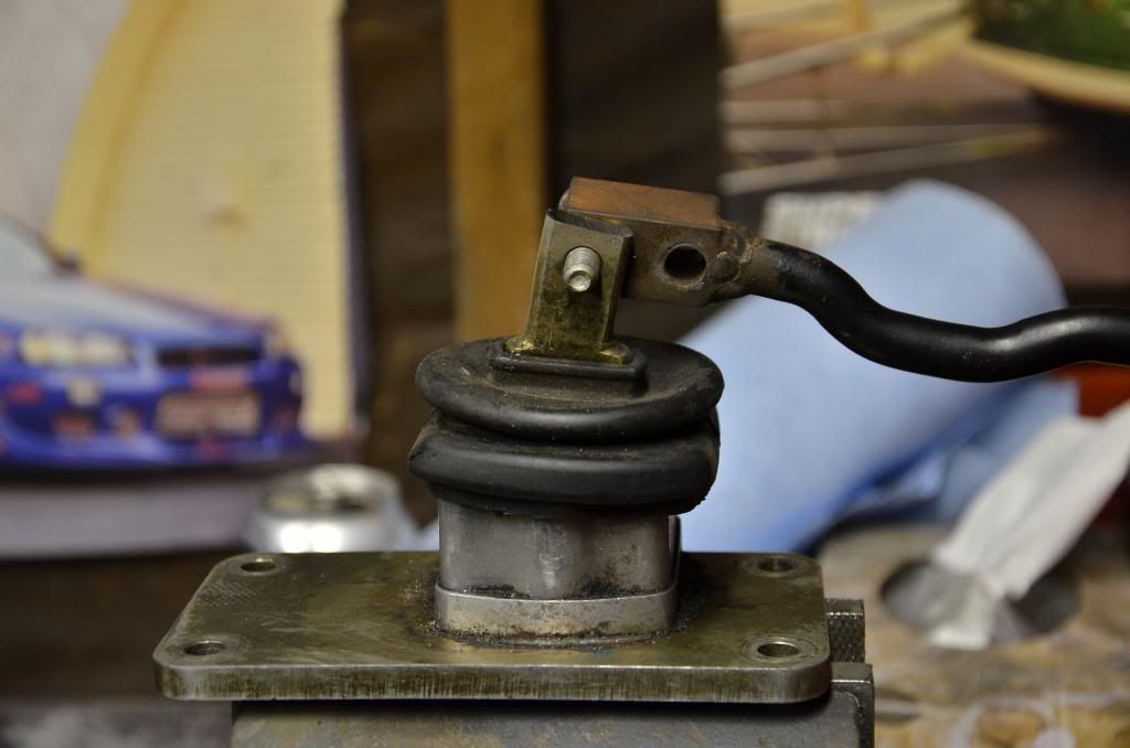
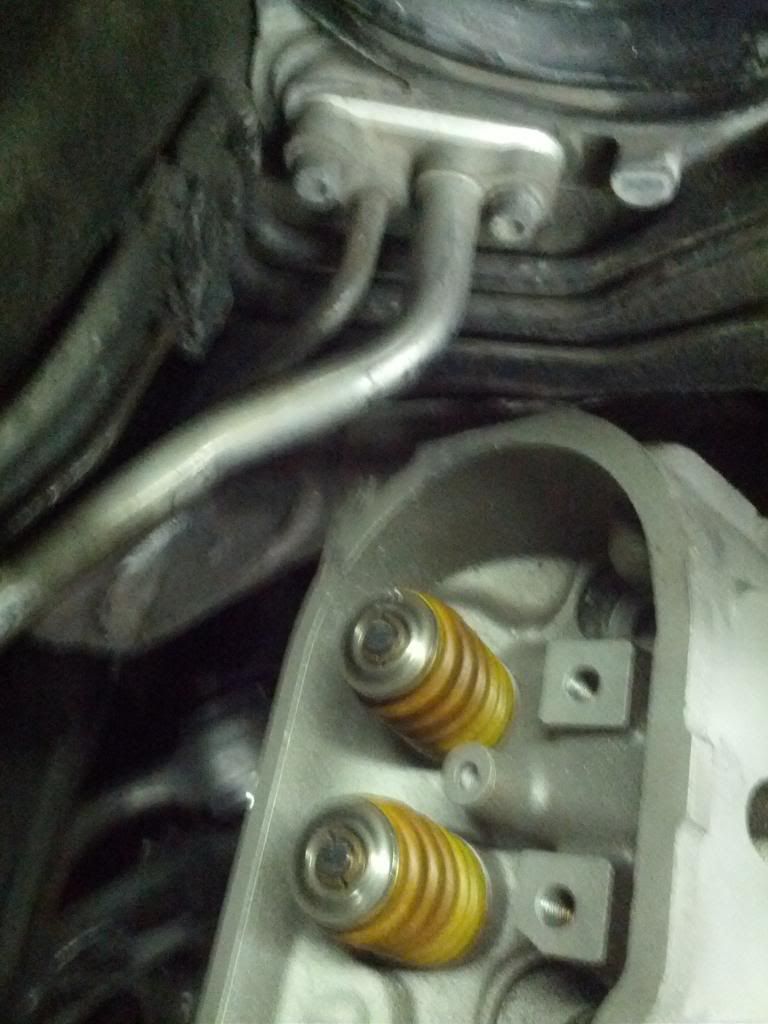
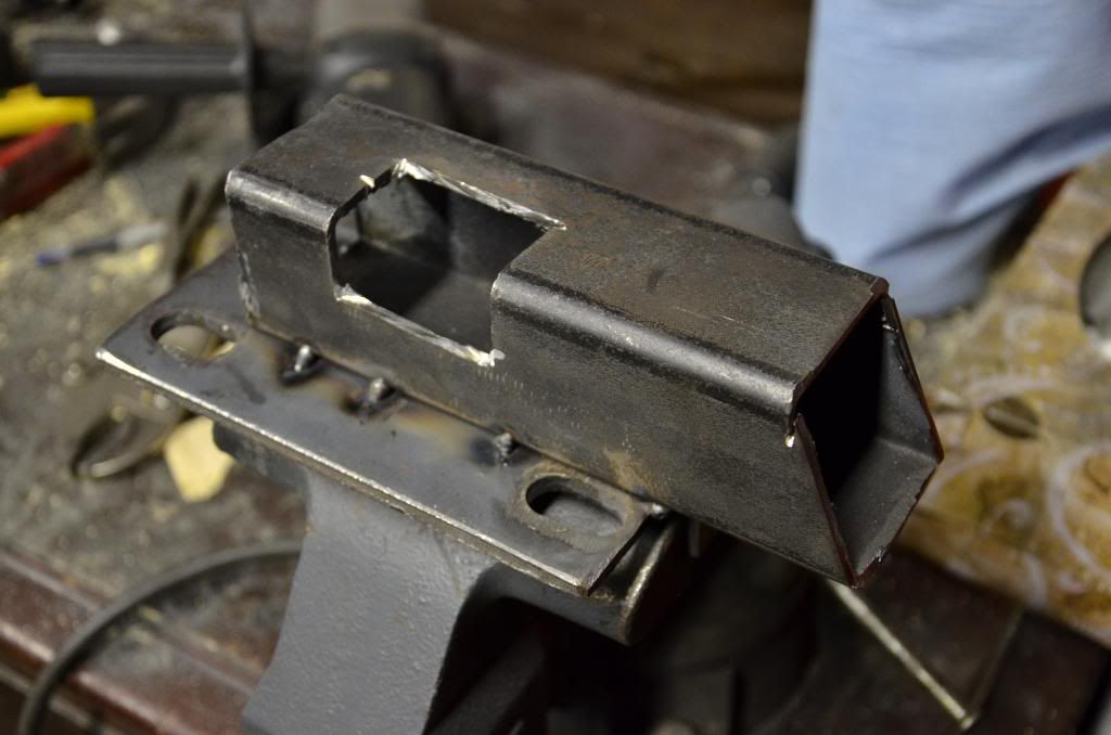
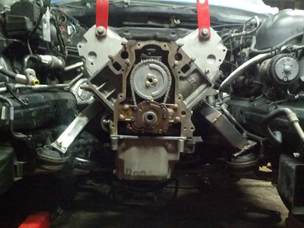
I had the sheet metal shop at work punch me out a few engine plates, bolted those to the motor. I also grabbed some short lengths of 2" square thick wall tube steel out of the scrap bin, those will be used to make up the driver’s side mount around the steering box. I did a rough “from memory” sketch on CAD at work of the driver’s side mount. The passenger side will be easier, should be just one length (straight shot from the engine plate to the rubber isolator). My little farmhand MIG welder is wayyyy too shitty to actually weld all the way through and get full penetration so I’ll just be tacking the shit out of it and having the shop at work weld it all up for me. exhaust should be okay to weld due to the thinner wall pipe, I’m just a crappy welder, but this will be good practice.

Should have some spare time tomorrow on my day off to finish trimming the GTO pan, maybe start to cut up the tube steel to make the mounts.

playing with fitment

i was thinking about this for a plate when i’m done…

http://farm9.staticflickr.com/8083/8315002706_e711831f02.jpg

ITSA GMW

there’s a guy over on Bimmerforums with a high budget E39 LS swap that had a radiator air deflection laser cut with his own little logo.

---------- Post added at 08:20 PM ---------- Previous post was at 07:52 PM ----------

finished cutting up the pan, it clears the crossmember now.

slapped it on the block.

placed a 1" thick piece of wood under the pan to simulate space between pan and crossmember, and a 1"x1" piece under the pan on top of the steering linkage.

unfortunately, the motor needs to be forward enough to make the oil pan happy above the crossmember, but this makes the shifter pissed off. it’s about 3" forward of the shifter hole in the unibody. had to modify the stock shifter to allow the rear of the trans to come up vertically as much as possible, to give me the right driveline angle. it was hitting the inside of the trans tunnel, making the rear of the trans point down at a 8* angle. i might use a GTO shifter (offset to the rear by a bit compared to the Camaro one).

stock:

moved the shifter rod down “one hole”

cut a top inch or so off, bought me some room.

Whats the plan for the oil pan?

what do you mean? it’s all set as far as cutting it up so i’ll have the guys at work cut out aluminum patches and TIG it for me.

---------- Post added at 08:43 PM ---------- Previous post was at 08:34 PM ----------

slapped the inclinometer on the bottom of the car on the frame rail, only place where the car was parallel with the ground.

that’s with the nose pointing up.

after cutting the shifter i got this.

rough height in the bay. rotation along the crank axis is a bit off obviously but i’ll fix that the next time i work on the car.

You should sight in the drive line angle, it should be less then 6 degrees

I have the flu and its been awhile but is the oil pan not backwards?

what do you mean, “sight in”?

the engine is nose up 5.8 degrees, and the car is also nose up 1.2 degrees (level of ground). subtract 1.2 and we’re at 4.6.

nah you’re not high. 99% of LS pans are rear sump. with the BMW V8 crossmember you have to use a front sump pan, the only one that’s OEM (aka cheap) front sump is the LS1 GTO.

Good stuff. :tup:

Why not use the eBay studs instead of the arp bolts?

i’ve never even heard of ebay studs…

since heads came off to replace head gaskets and check things out, head bolts had to be replaced anyways, so i figured i’d go with ARP.

ARP head bolts are fine. Like this project, keep up the good work.

so, let’s begin with tonight’s pleasant atmosphere! before i fired up the heater it was 32, as i finished up for the evening i snapped this.

i really wasn’t happy with the pinion angle, and the only thing that could give was the shifter moving up into the tunnel. so i enlarged the shifter hole forward about 3-4".

fun fact…burning tunnel insulation smells like pickles

so this places the engine fore/aft roughly where it will be, give or take half an inch.

head to AC line:

tight spot by the steering box, 2" square tube is very very tight, i will end up notching the mount around there to avoid any contact if/when the motor moves back and forth.

this gave us a better angle than last night. remember that i’m subtracting 1.2 degrees of the car’s nose pointing up.

grabbed some stock from the scrap bin at work and put a 90* bend in it with the vise. cut up the stock shifter rod (where the knob threads on) and welded on the threaded portion to the stock. i purposely left it tall so i can cut it down later to my liking. i actually really like it tall, gives it that old muscle car feel.

with das boot on it:

tomorrow i’d like to finalize the location of the motor and start to make the mounts.

nice progress

Cost less than arp bolts, are studs, are proven to work great

the ARPs are sitting in my kitchen so i’m going to use those, but thanks for the heads up.

decided to not use a GTO shifter since using a steel bar gives me the flexibility to bend the shifter however i want as well as shorten and lengthen it.

final engine placement. measured pinion angle for the final time, centered motor left to right both at the crank snout and at the trans output.

compound angle i’ll have to cut

beginning of driver’s side mount. the notch is to clear the steering box bolts. it’s 2" tube steel.

been busy over the last few days.

3 cutoff wheels, a lot of 2" tube steel, lots of trial and error, and we have mounts!

everything as of now is just tacked into place for 2 reasons:

1: my 115V welder doesn’t have the balls to penetrate the thick wall steel
2: i’m a really shitty welder

i will be grinding down the mounts and wirewheeling them to prep them for full welding, which i’ll have one of the guys at work do.

looking at it now, that trans mount looks a bit crooked. tomorrow i will realign it and re-tack.