new OEM GM MLS 6.0 headgaskets, nice pieces. new head/block dowels since the old ones disappeared. new ARP head bolts torqued down in 3 passes to their specs, not GM’s.
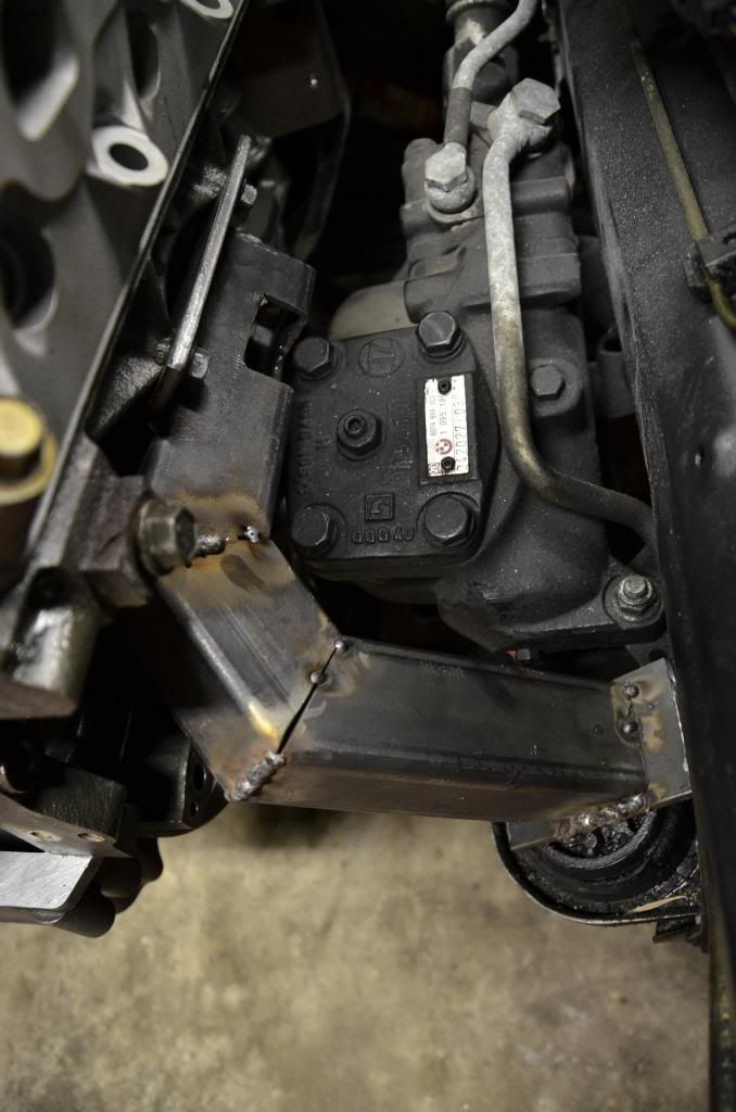
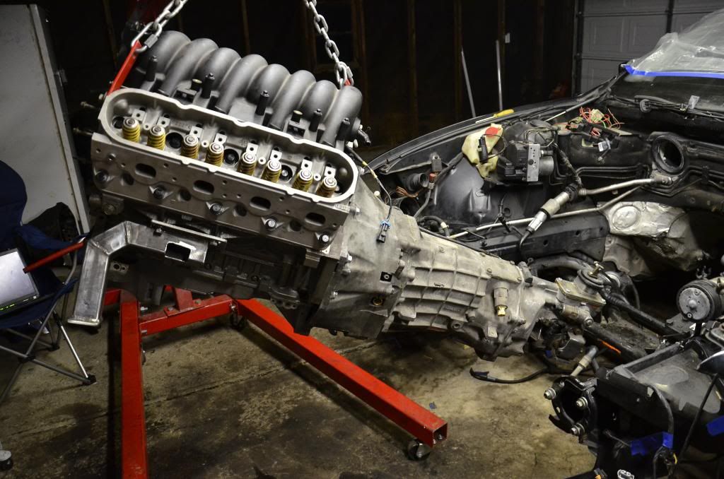
i had the mounts fully welded today at work and they came out awesome.
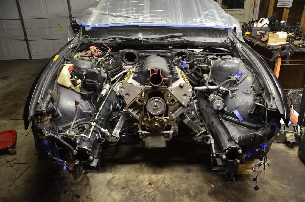
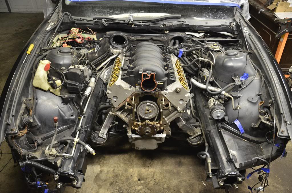
the motor still needs to come out to get all new front and rear cover gaskets and main seals, as well as to have the pan welded up and GTO pickup installed with windage tray. but, it’s in.
well of course there’s a goddamn problem…i was so concerned with clearing the steering arm (which is a moving part about 3/4" underneath the oil pan) that i totally disregarded hood clearance. it’s not terrible but i may need to figure out something creative.
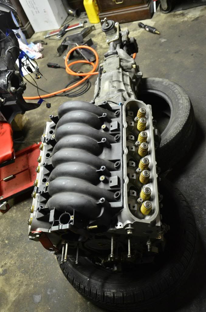
truck manifolds didn’t fit on either side…but i’m keeping them, since i might boost this sucker at one point.
have to start the headers next. i have a pair of used shorties i can hack up and modify. i also have an old tubular stainless header left over from my SE-R Spec V that i can chop up. Always prefer to use what i have rather than buy new.
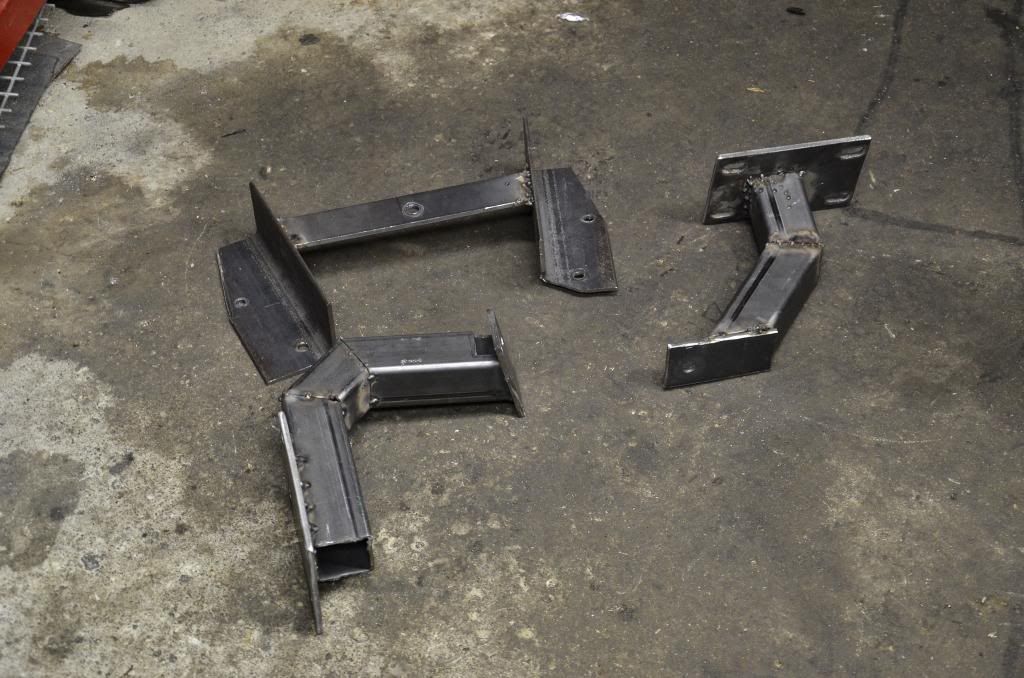
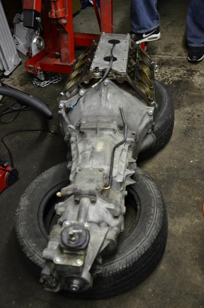
junkyard engine, transmission out of a wrecked Camaro, mounts made out of steel that was pulled from a scrap bin…i’m sensing a trend here
I’m usually not one to say something negative in a build thread…but those mounts really don’t look like they’ll support that powerplant, and I don’t mean because of the welds.
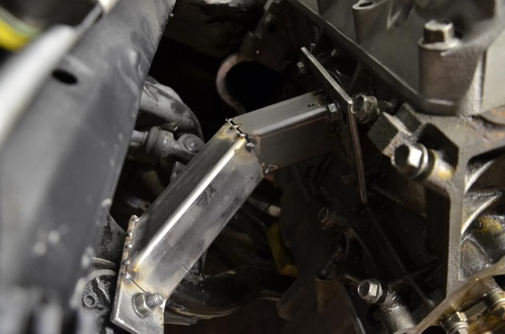
that driverside one makes me feel like someone divided by zero. I’d want to make a cardboard template to weld a piece of 1/4" plate like a shark fin along the top side to tie all of those pieces together and act as a major gusset. Probably would do something similar on the other side too.
appreciate the input, but there’s literally no other way to route either of the mounts. i based mine upon a set produced by a guy on bimmerforums. his don’t have a notch for the steering box, so they must be smaller (probably 1.5" tube steel). i overbuilt mine using 2" steel, welded at every junction all the way around. i’ll be monitoring for any cracks, but i don’t expect much trouble since i’m running stock M5 rubber mounts (not solid) and stock T56 rubber mount (for civility–it is a summer daily after all). it’s also not cammed as fuck so it won’t be vibrating any more than a standard LS would.
for what it’s worth i was shocked to see that the OEM BMW M62 mounts were cast aluminum, of all things.
i had problems with the design as well (more so the amount of offset leverage/strain at the single mounting point to subframe) but if hes comfortable with it then he can do as he wants. it appears that he is doing things right with paying attention to angles and such instead of just shoving it in there so the progress still gets a :tup:
The steel mounts, although at a 90* angle to the load, still have the force directed down into the rubber isolator.
Someone who is doing the same swap on bimmerforums made a great point: a steel member could go directly straight to the rubber mount and load it like that, or, it could loop around the entire engine, and then come back and mount to the rubber. Either way, the rubber mount doesn’t care, as long as the loading is the same, and the steel can take the stress.
My stock rubber mounts are all torn and shot, which makes them very flexible. This actually kind of came in handy, since when the weight of the motor laid on the rubber mounts, they would have exaggerated the deflection caused by any torsional loads in any direction. They didn’t move a bit, everything stayed the way it was when they were unloaded.
New rubber E39 M5 mounts will be here tomorrow (and the rubber is a stiffer durometer to boot).
Also on the hunt for some 98-99 LS1 tubular stamped steel exhaust manifolds. The truck manifolds don’t fit and it might take more time than I’m willing to put in right now, to make the LS1 aftermarket shorties I have, work.
the weight of the engine is coming straight down. mounting point of the car is forward of the engine. you have a single attachment point with a flat plate where the motor mount is welded to the plate behind that single attachment point. the weight of the engine is redirected into the motor mount which is directed to a point behind where it attaches. think of it as a lever. there is far more force to the back of the attachement point then what is centered on the attachment point. that causes a much higher load on the attachement point then if that weight was centered on it. i dont care what the guys on bimmerforums say. just because they do it doesnt mean its right. will it work? sure. will it fail? possible.
thanks cougar, i don’t think they’ll work though. they’re cast iron anyhow. i bought a set of tubular stamped steel 98-99 manifolds on ebay for cheap that will work. i’ll sell the shorties i bought now, and keep the truck manifolds for if i eventually go turbo.
derek, thanks for your input. time will tell. i’m confident in them.
tilt in the engine is necessary for tunnel clearance as well as compensating for the wedge machined in carburated manifolds, sometimes to compensate for large differences in height between transmission output to rear end height, but you def want to make sure pinion angle is acceptable.
you also need to take into consideration “axle wrap” on hard acceleration when determining pinion angle, however that wouldnt be an issue on the irs…
Motor plate is proof that if a little is good, a lot more is terrible. Certainly isn’t common place under a BMW hood for sure though, gotta admit that. lol
should, is the key. is it safe?? come on he is using small hardware, wrong steel. Come on some one needs to take a step back and say "Can you build a “LS BMW” = yes “Should you build it out of the scrap bin at work with angle iron and square tubing?”= not sure if that is the budget build, or just being cheap…
in this case I could see it being a cost isssue, would you like to pull the engine to change the ps pump?
i think some sort of plate, and mount design could work. But when in doubt, claim its a budget build and replace ujoints every 1k miles.