Sobo's Cluster F#$%...

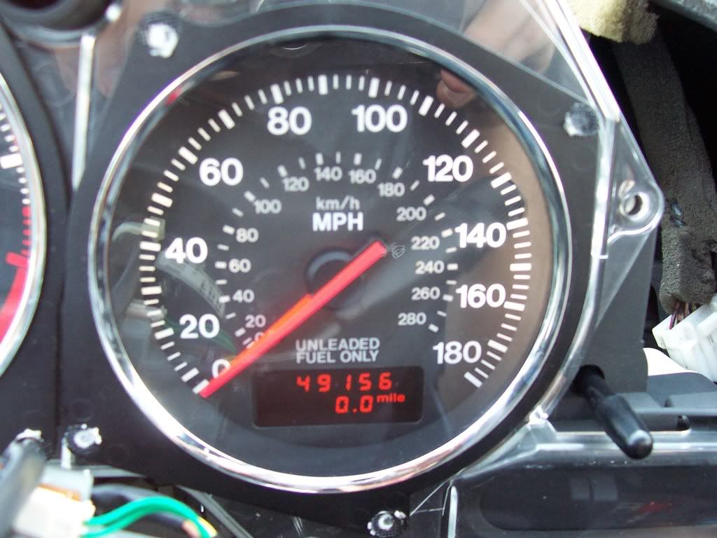
Sobo asked me to take a look at the cluster out of his RX7. The odometer was not working and there was an issue with a flickering LED. The LED was an issue with the socket. I had to modify the LED leads to make constant contact on the base (No pics of that).

This is how I fixed the odometer. There really is not much info here but maybe you will learn a thing or two or ask a question…where are all here to share, right?

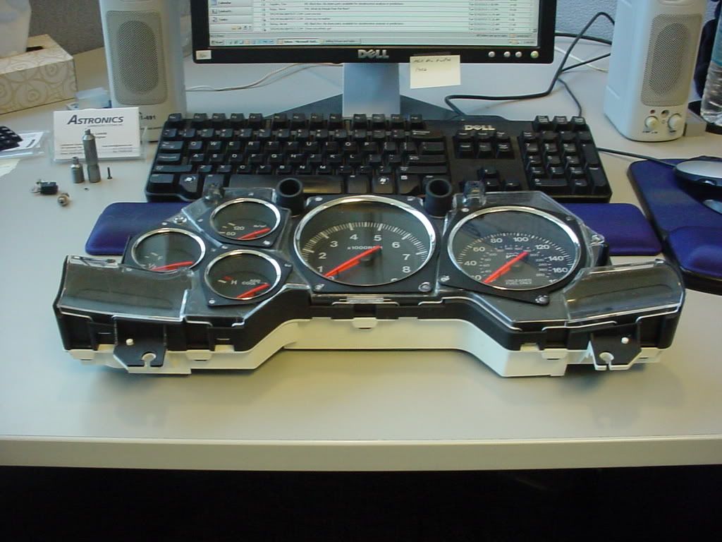
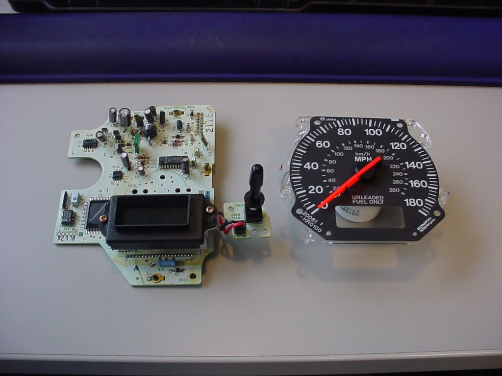
Here is the cluster untouched.

Ok I touched it…

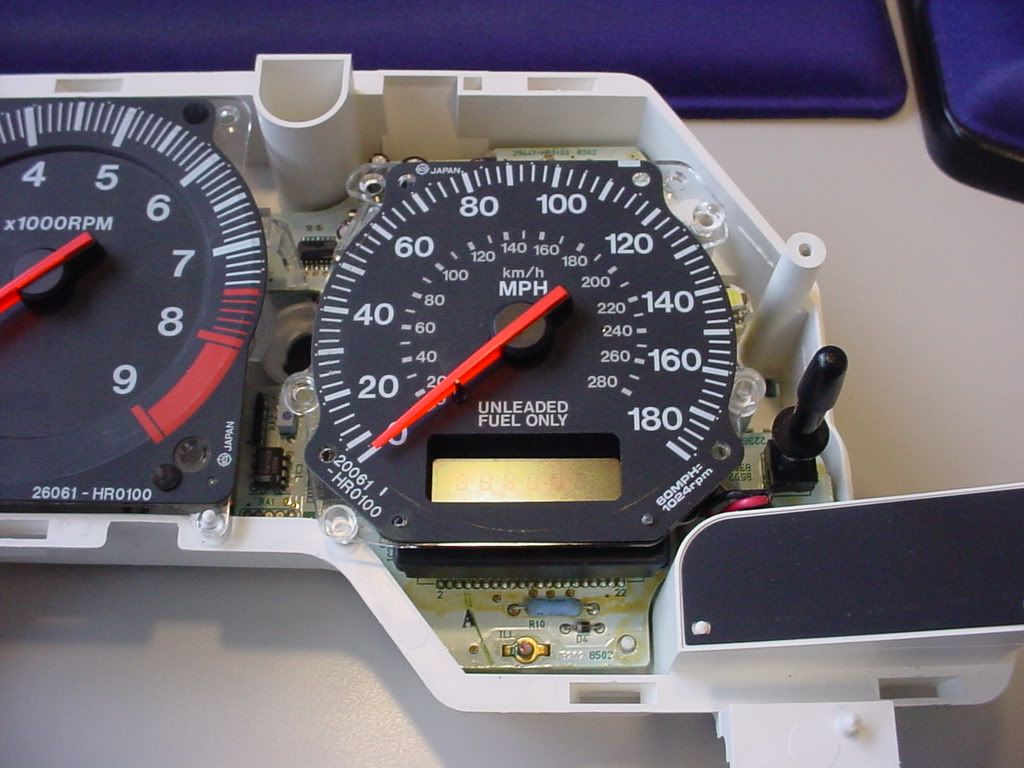
Closer inspection. You can see something happened.

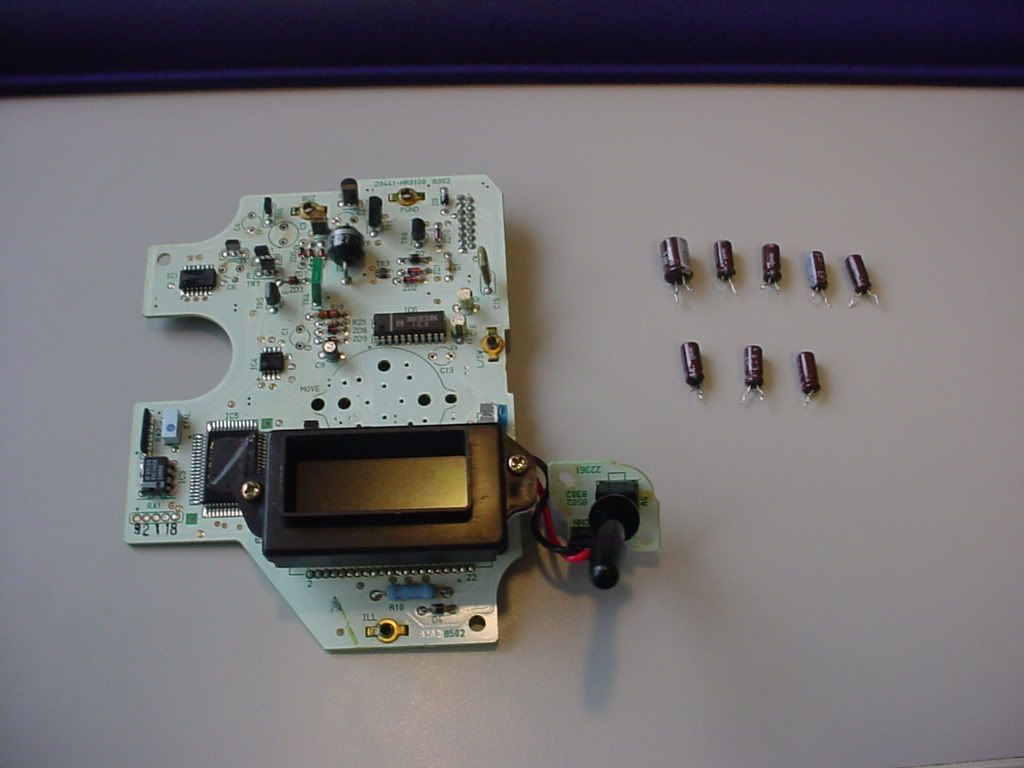
Then I pulled it apart.

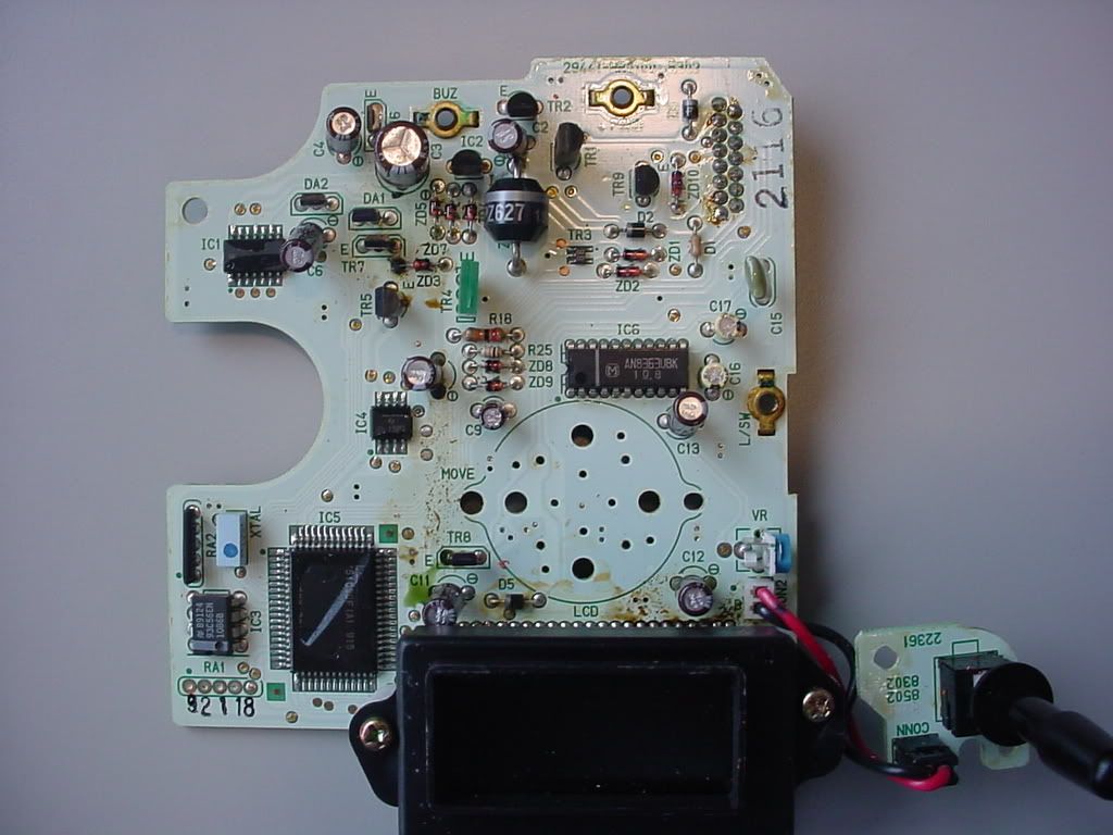
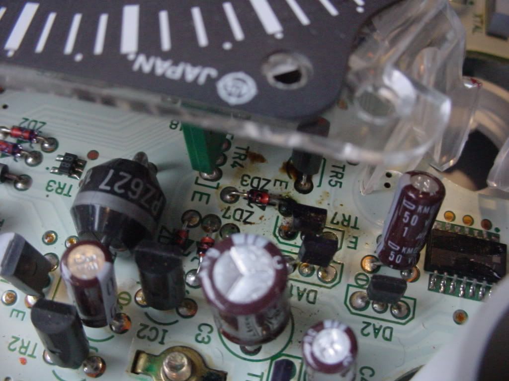
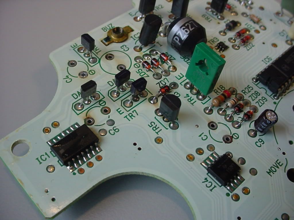
CLOSER Inspection. Ugh. Yummy.

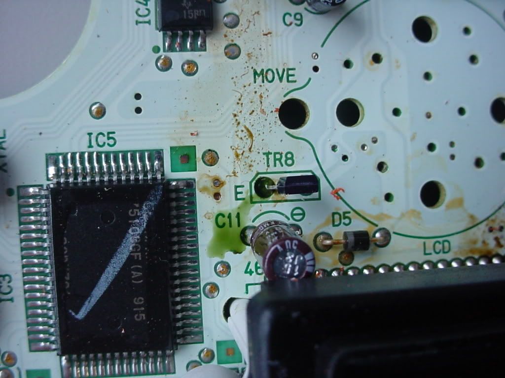
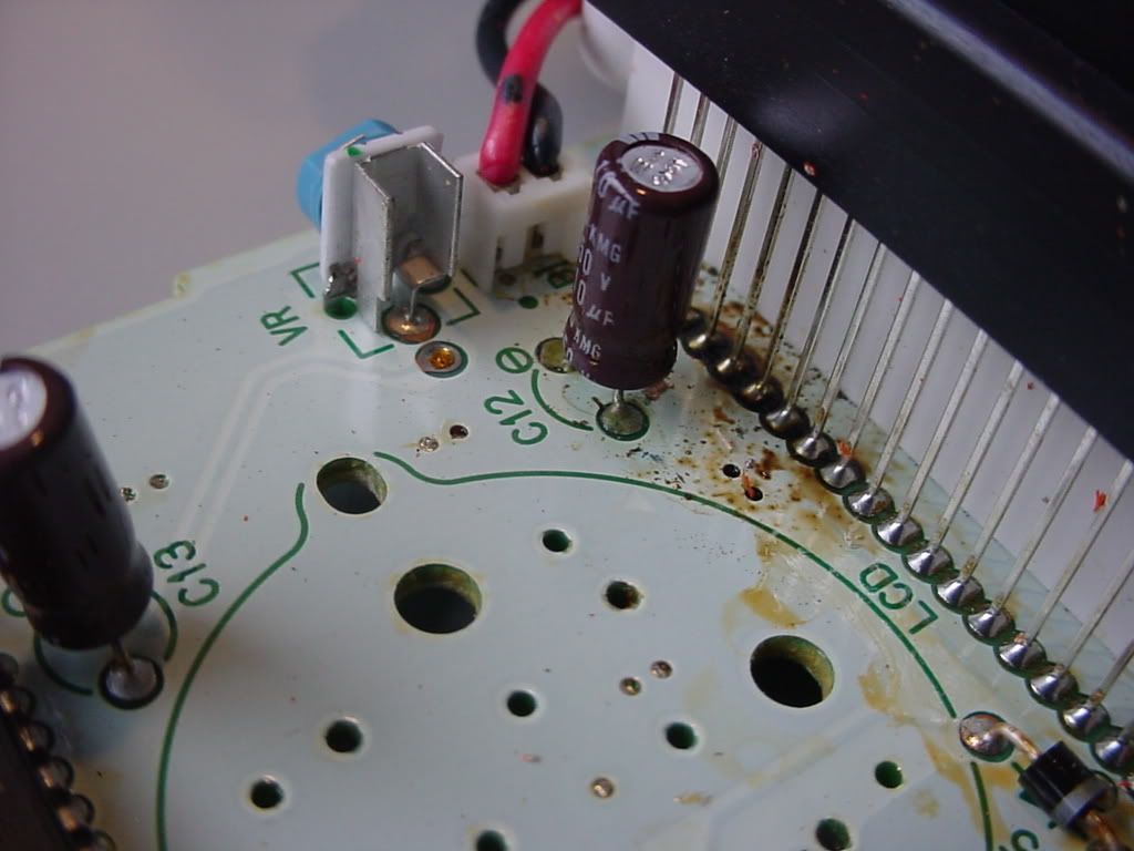
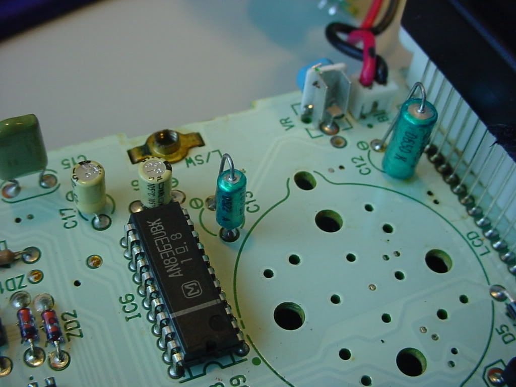
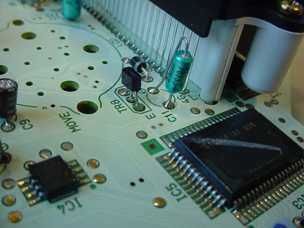
Capacitors C1, C3, C4, and C12 where shot. This is commonly know as “Capacitor plague” in industry today but was not ruled a failure point until early 2000. Over time the capacitor literally “cooks” which leads to leaking electrolyte. This causes the component to fail. I ripped all potentially “Bad” capacitors out. Based on their size and rating it is pretty easy to weed out the bad ones.

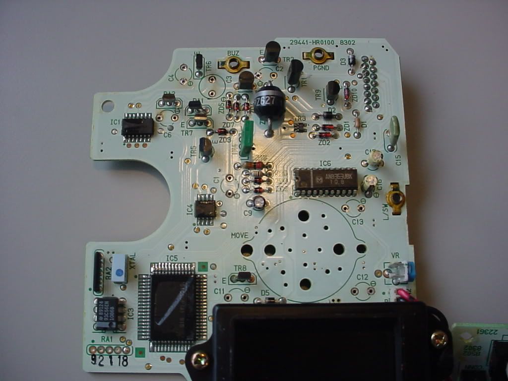
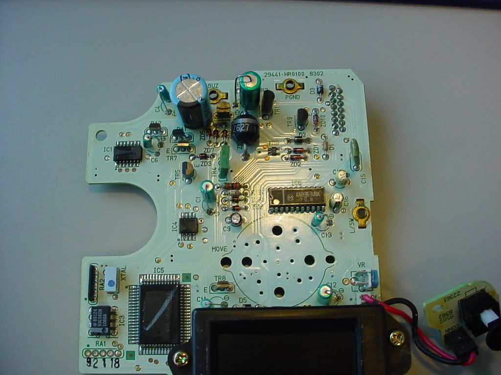
Then cleaned the PCB. If you have ever looked at a commercial PCB you see all the flux residue left over from their highly controlled processes.

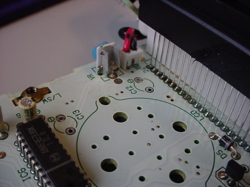
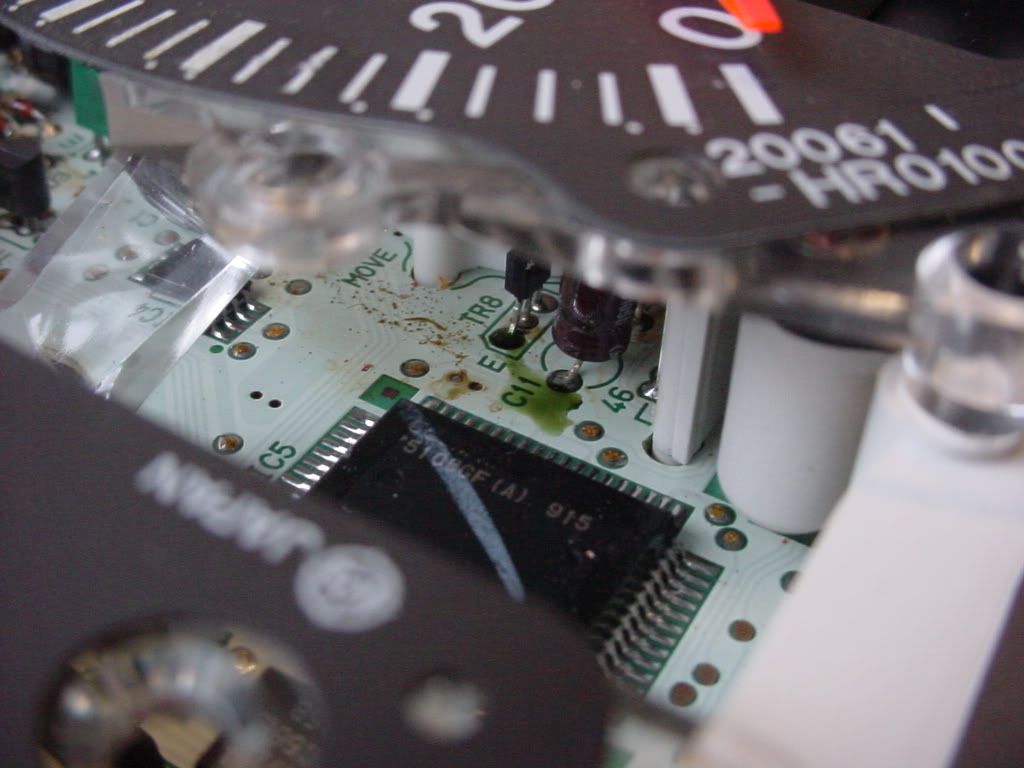
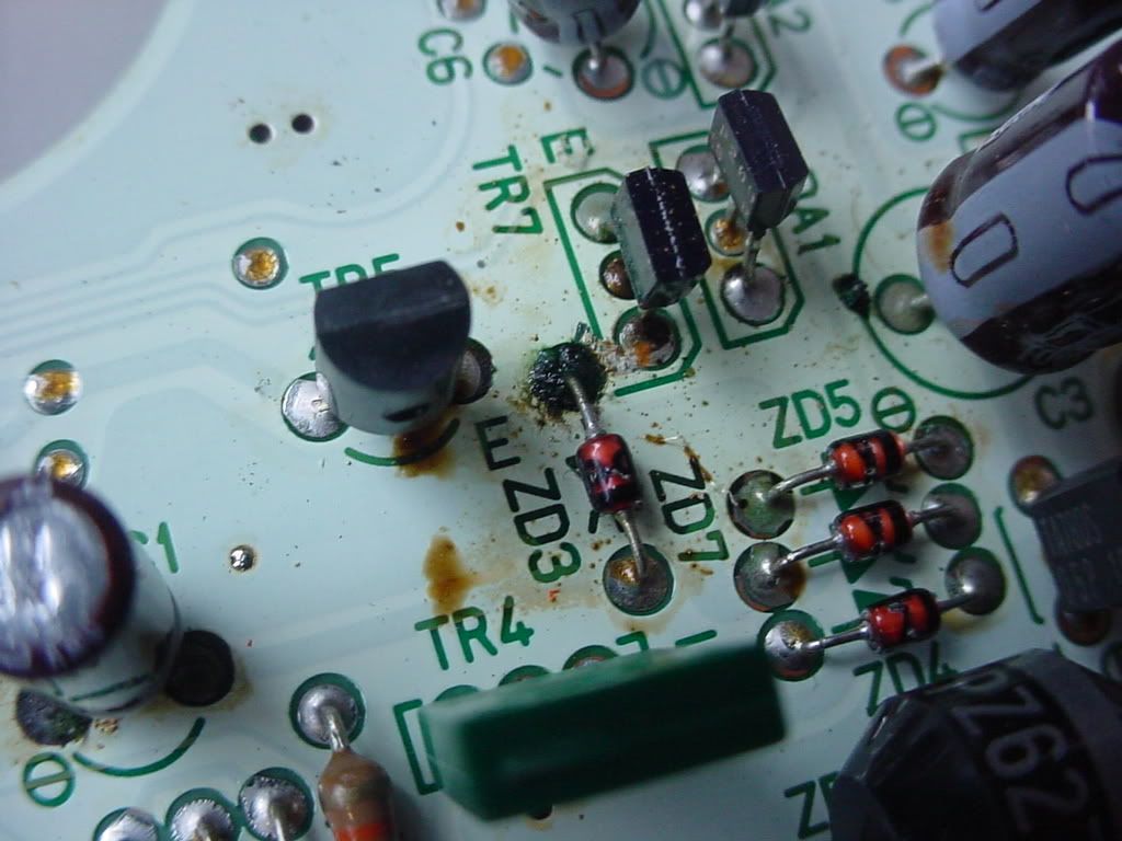
I tested each part that appeared damaged. This Zener Diode was pretty beaten up at the solder termination on the Anode. However, the part itself was good. I removed and resoldered the joint. Much better.

(Again for reference)

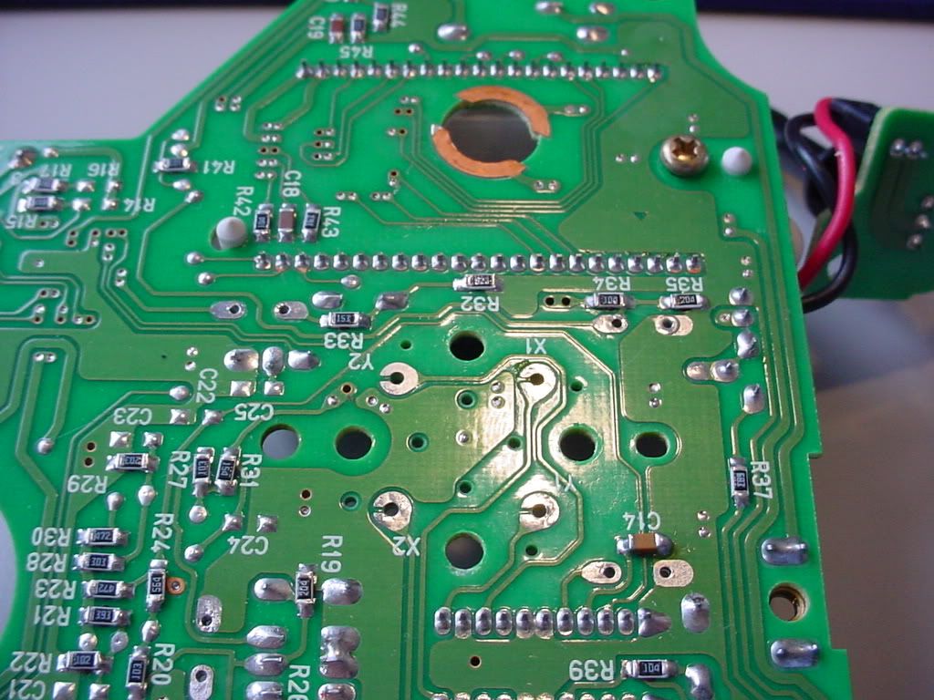
I didn’t grab a shot of the dirty PCB rear but all the LCD pins, Speedo pins, and large thru-hole parts had a lot of residue. It is unrelated to what I am doing but I cleaned that anyways.

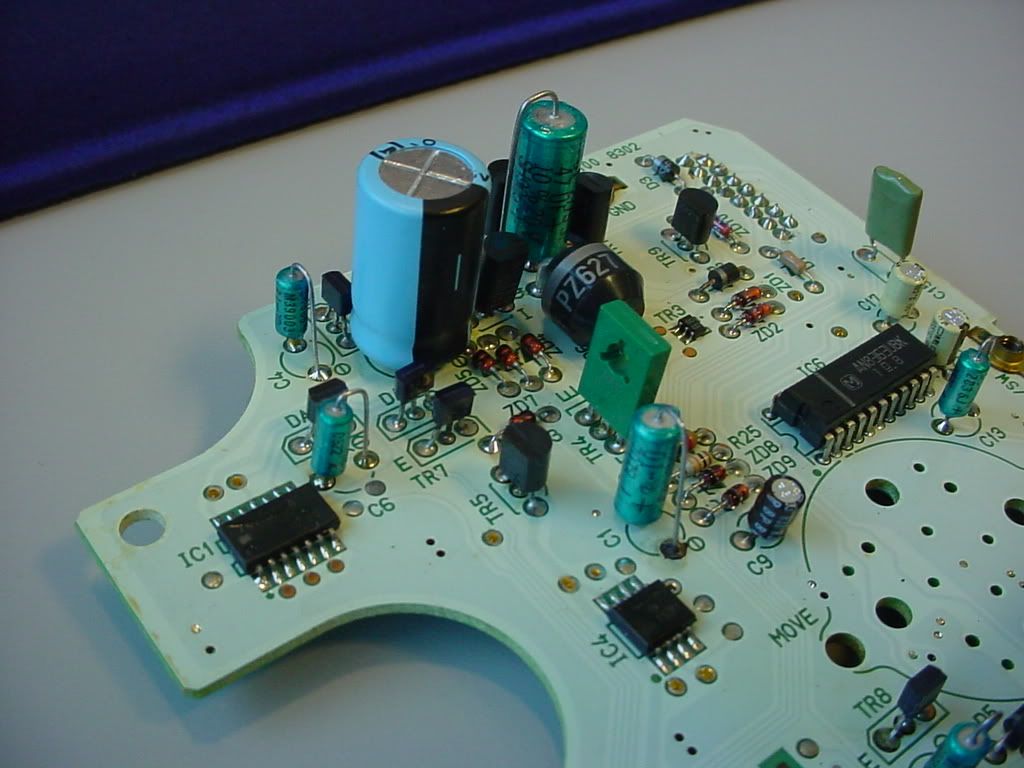
With the bad Caps out and the board ready to go I bent, terminated, and cleaned the new parts. I replaced these caps:

  • C1 - 10 uF
  • C2 - 47 uF
  • C3 - 1,000 uF
  • C4 - 1 uF
  • C6 - 1 uF
  • C11 - 2.2 uF
  • C12 - 10 uF
  • C13 - 1uF

I switched to a solid axial Tantalum capacitors for most of the radial capacitors I pulled out. The solid Tantalum is highly reliable and will virtually not break down. The 1,000 uF cap I replace with a new electrolyte, but this time I switched to a larger wattage capacitor. While the component is much larger I was able to fit it on the PCB. This allows for a lower risk of being overdriven and potentially no risk of breakdown.

All done and back in service.

Before you toss that used non-working part in the trash, take it apart and try to fix it. Or, shoot me a PM.

Total part cost to fix: Around $5.
Total time to fix: 10 hours.

Nice work as always Lucas!

Bro, you do some good work - that’s black magic to me! :tup:

Awesome Luke, and great thread title!

I love your DIYs

fucking voodoo my friend.
In the event I have something of that matter fail, I’ll just call you.

WOW.nice work!

Damn, thats pretty impressive.

Slightly OT, but would have have access to anything that you could find out specific resistor sizing on an amp? I have a kicker 250w that died and a friend said one of the resistors is shot and kicker won’t tell him the size. He tried testing it but it didn’t work, IDK why I don’t understand this stuff.

Damn! Great work man! :tup:

I’m stupid.

lulz exactly how i feel after looking at that

Damn popping capacitors. We lose a ton of motherboards here at work the same way.

Noticed the Astronics card on your desk. Congrats on the new Airbus contract.

:bigtup:

10 hours! Goddamn!

Great documentation :tup:

10 hours… 5 dollars… sure, if i was knowledgeable enough to know what i was looking at, id see dirt/grime and say… “let me clean that up… oh shit, still broken” now i wasted a few hours, and its still broke…

so ill jump on ebay and buy a used one for 200 :)… lol

Nice write up btw.

Cool DIY. What’s your day job Luke?

I understood none of that

:tup: to getting it working though lol

impressive work! now can you roll back my odometer now?..j/k

Thanks for the comments everyone. I would be happy to help anyone out with stuff like this or try to steer you in the right direction.

If it is a resistor only issue you could just look at the resistor. They are “marked” either color coding, part number, or sometimes even on the board (but this is unlikely). It is hard to diagnoise an unmarked component but there may be a way to do it. The simplest way would be to find a working one and just measure it. The hardest way, and very dangerous, is to make an educated guess based on the circuit design. I do not reccommend just throwing in a “guess” as this could cause even more damage. But I would be willing to look at it for you.

Thanks. It is a good amount of business for us too.

Haha. Most of the time is tracing what is broke versus what is not broke. Also, taking apart something that is not meant to be easily reworkable take time. I had to de-solder the speedometer to get it off. Some of the copper planes on this were rather thick. It takes time…:shrug:

---------- Post added at 10:17 AM ---------- Previous post was at 10:14 AM ----------

Manufacturing Eng by trade, Mechanical/Industrial Eng by Education, Electrical technician through work experience and DIYs.

how much do you charge for work like this/led conversions and such?