This thread I will talk about how we are building the intake manifold for a 1.8T VW cylinder head. One of the many custom pieces going into the Jetta race car: http://shift518.com/showthread.php?t=20487
Starting with what pieces I know I wanted to run; AEB large port runners, 75MM throttle body I got to crunching some sketches in SolidWorks. Solid works is nice because it allows you to quickly design the manifold, see your ideas in 3D and catch any physical design flaws quickly, prior to eating up materials and time. Also included in SolidWorks is the Flow Simulation tool. This allows you to flow test the parts with many different variables, to get a good idea of how the manifold will act in the real world. You can animate it also, and with inputting the cam profiles, timing, RPM, etc. you can actually open and close the “lids” on each runner just as an intake valve would on a motor!
Now to start this, I am by no means an expert at Solid Works, mechanical engineering, or intake design. This is the first manifold I will produce from scratch, so i am way behind the 8ball here, but I have been researching this for a few months now, and reading ALOT of information about this entire process. If anyone has even gotten the chance to use Solid Works, it will take you a week to make a simple bolt! Lots of seat time is required to fully understand it. BUT with some friendly tips from friends (BoxerSix and Mafdark) I am getting the hang of it.
So lets get to the good stuff.
Started off by going shopping. Ross Machine Racing sells all kinds of stuff to build an intake manifold from scratch. I picked up some 1/2" flat stock for the plenum floor, a 2 foot section of their 5" D shaped plenum, some 1/2" stock for the TB plate and a D shaped end cap.
I knew I would need an AEB intake manifold to start with. Idea is to simply use the German engineering they already put into it and hack the top off it! One pass across the band saw and i had just the runners left. After that we machined a slight recess into the 1/2" flat stock to position the runners in and help weld in position.
At this point I had to design the plenum. Now allot of people out there just weld on the D shape plenum cap the end and slap a TB flange on it and call it a day. Sure this will increase the volume of the intake but how equal will the runners flow? Some good reading material with just this information is here to give you a good idea: http://forums.vwvortex.com/showthread.php?3098525-1.8T-Intake-Manifold-Test-Results
Notice the Homebrew AEB lower + RMR D plenum. Total flow is much higher than stock but look at runner #1, its seeing far less flow than the other 3, and even they aren’t very close together. That would create a slightly richer combustion in cylinder 1.
So this is where SolidWorks comes into play. I designed the manifold with the AEB lower and the simple D plenum on top and added a 75MM TB to it for an inlet. This is what it looks like. The inlet boundary condition is set to 10lb/s and the outlets are set to ambient pressure.
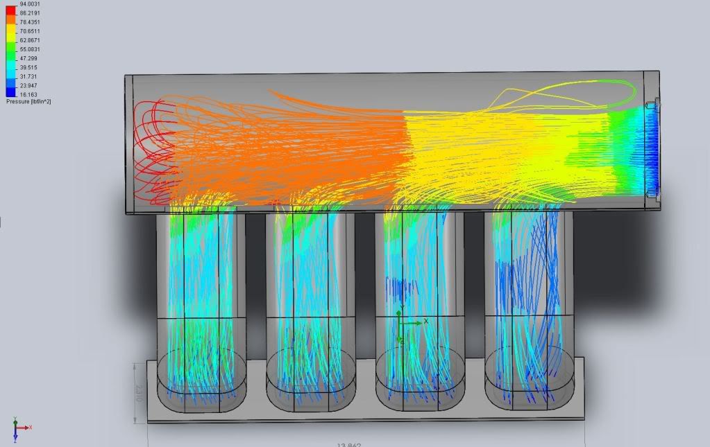
Notice the turbulence and the uneven flow into the runners.
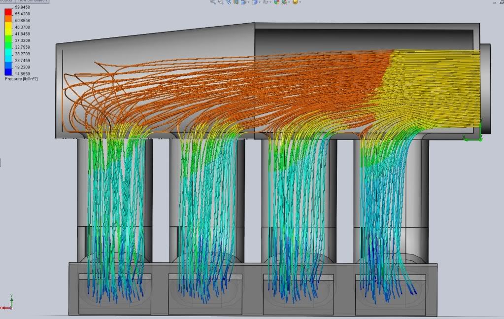
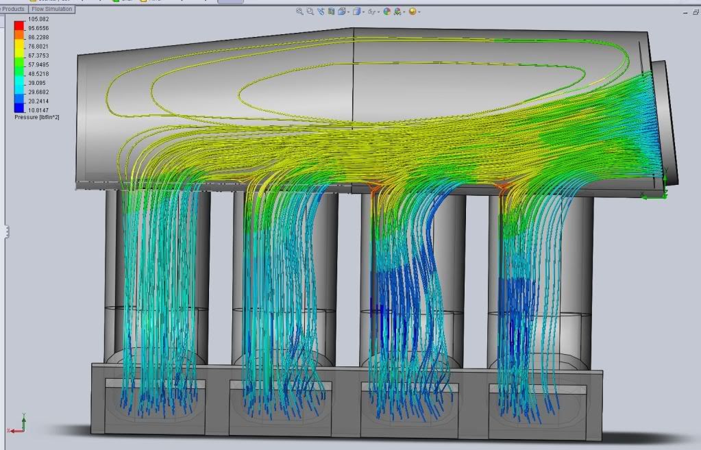
Now look at what just the tapered plenum after runner #2 and a .5 deg angle on the throttle body does for things.
Same taper on the plenum for the rest, just changing the throttle body angle +2 deg or so each time:
88 Deg
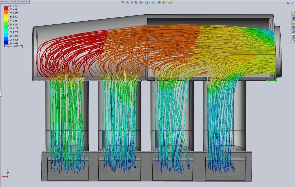
85 Deg
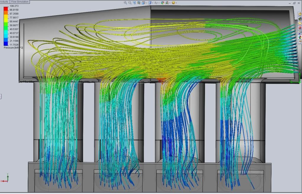
82 Deg
81 Deg
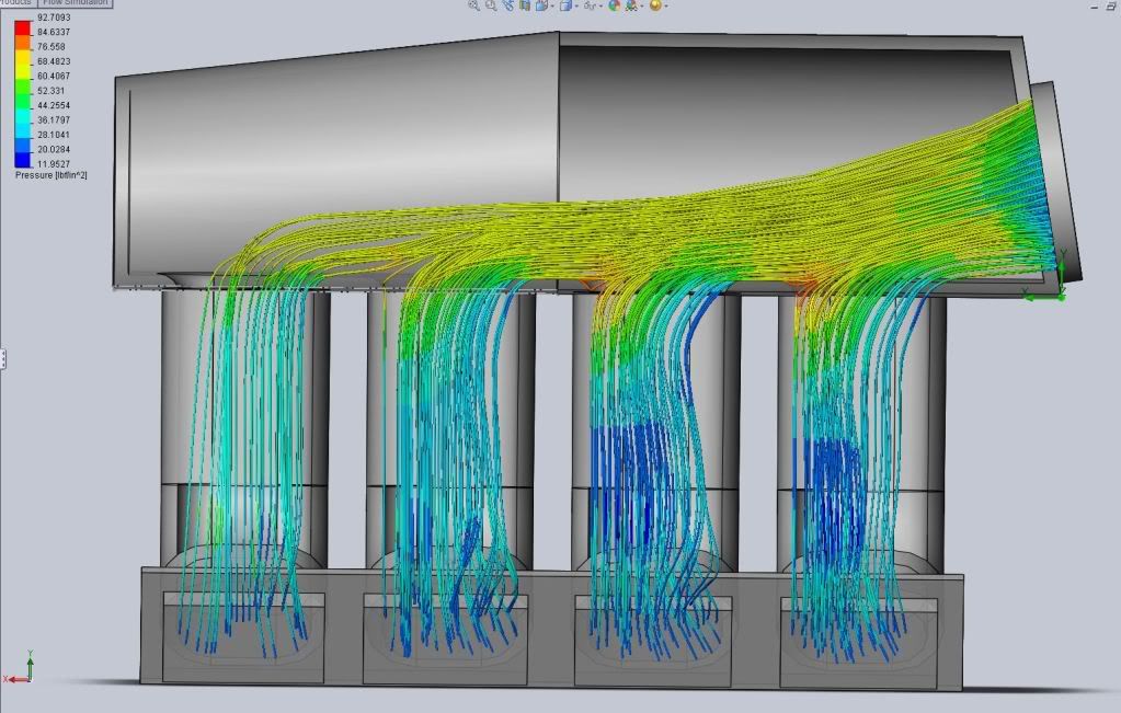
79 deg
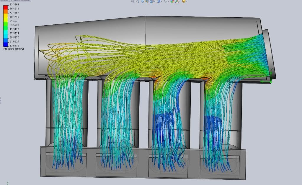
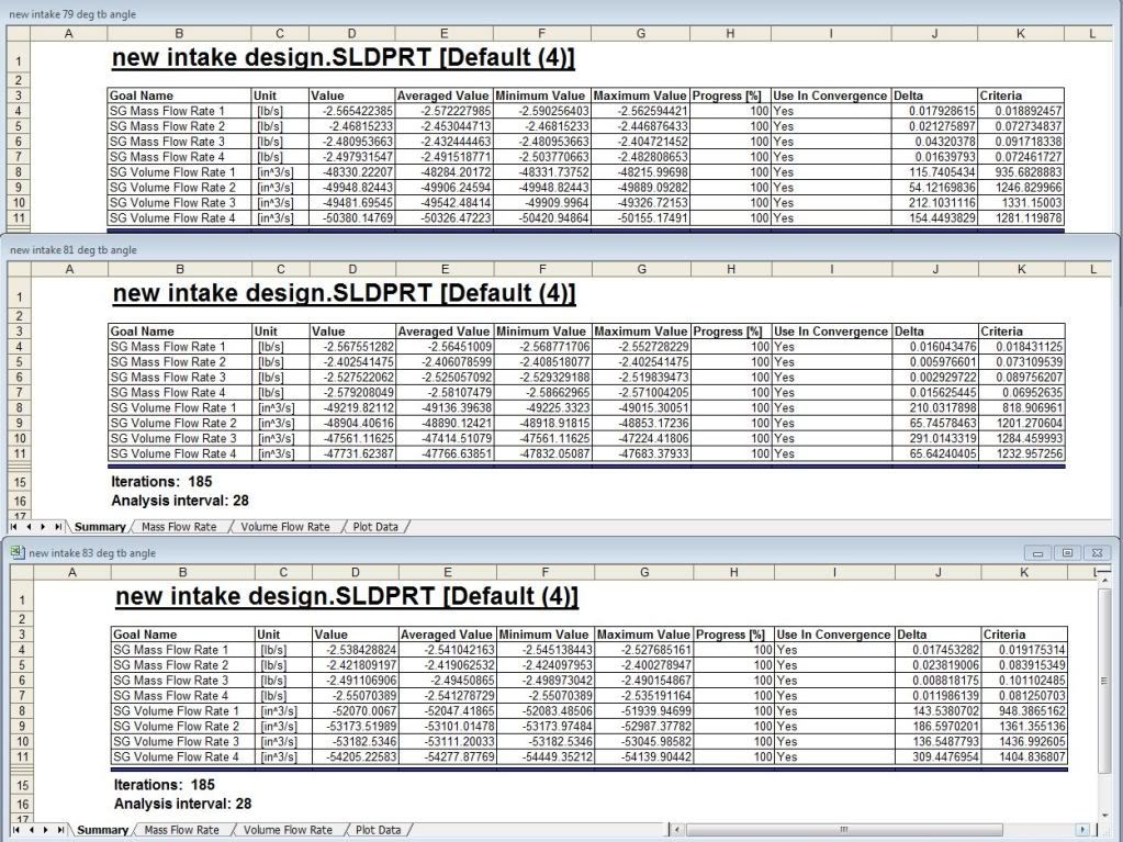
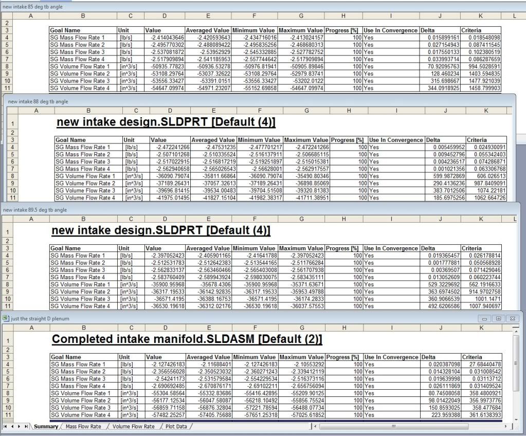
You can see how there is a “happy medium” with the throttle body angle. I am thinking between the 85 Deg and the 83 Deg ones would be the best.
Here are the numbers for the surface goals I set too help prove the changes.
I will pick this up in the next few days. I am finishing up the intake floor tonight by smoothing the transition into the runners and adding some material where its needed. Once that’s finished I am ready to make the final cuts and weld the rest of the plenum up.
Adam, Mike & others… please feel free to chime in if you see some flaws or think I am on the right path.