In a running engine, forced induction especially, the valve cover and crankcase vented air contains oil/water vapors. Stock vehicles simply recirculates the air back into the intake system and do not vent it to the atmosphere. This is done by the PCV components under your hood. The down side to this is the oil vapors get passed through the engine and into the combustion chamber. On many cars the inlet for the recirculation is pre MAF, so it can dirty up the sensor and cause issues. Forced induction cars have many more issues because of this. The oily vapors will pass through the turbo and intercooler. The intercooler will grab the hot oily air and condensate it causing the intercooler and charge pipes to fill up with oily crap.
This is where a good catch can comes into play. The catch can grabs the oil/water vapor and condensates it, catching all the junk, keeping it in the bottom of the can. Then the exit of the can, could be vented to the atmosphere or recalculated back to the intake much cleaner than the OEM pcv systems do.
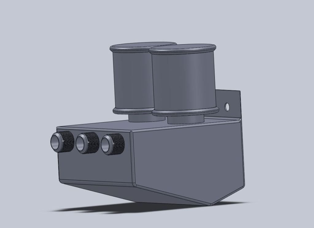
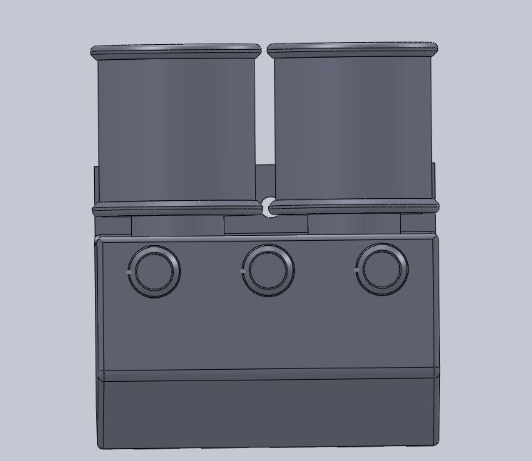
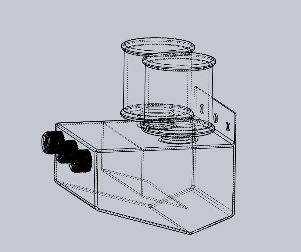
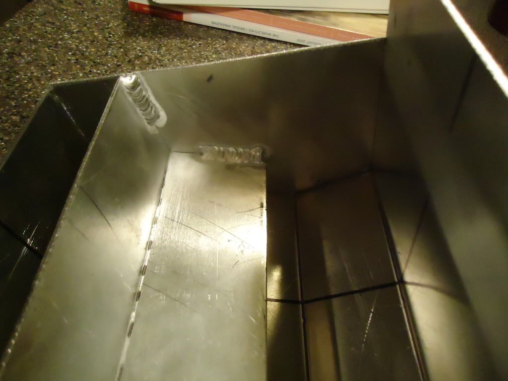
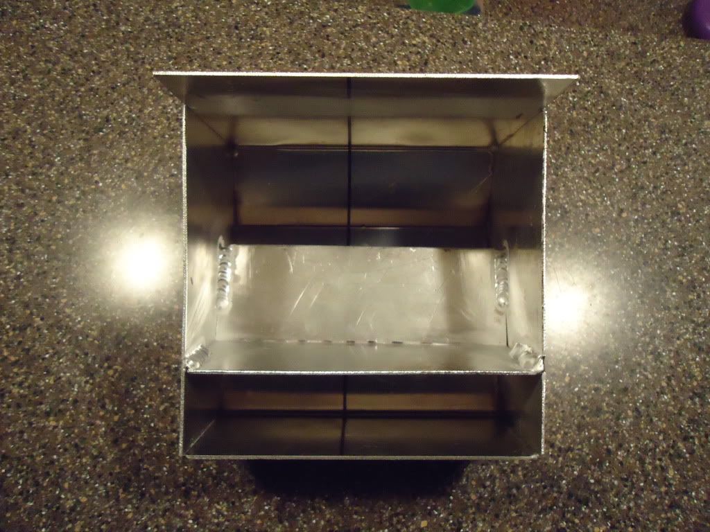
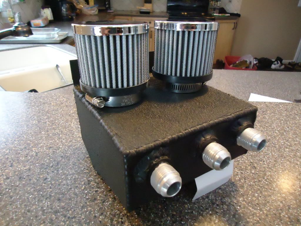
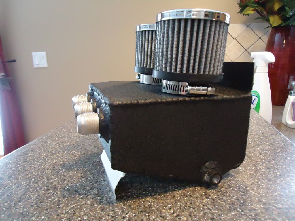
So here is what I came up with. Simple design, 3 (in this case -8AN) inlets feed the nasty vapors into the can where they slam into the face of an aluminum baffle, condensing and dripping down to settle to the bottom of the can. The entire can is made of aluminum, so as long as you keep it in a cool spot under the hood, the entire inside will help condensate the vapor and catch the oil and water. The bottom of the can is a V shape to aid in emptying the contents out the ¼” NPT plug on the bottom. This design vents to the atmosphere through 2 good sized filters, which will help catch any extra blowby that doesn’t get caught in the can. To keep it from blowing all over the bottom of your hood.
Its physical size is 6”X6”X8” tall. They do sell a slightly shorter filter that will knock an inch or so off the height.
Using the basic shape of the can, it can be built a few different ways to suit your needs. Any size AN fittings up to 3 an be used for inlets, hose barbs could be substituted, and the filters could be replaced with a single hose barb or AN fitting for recirculation needs back into the intake if desired. If you’re interested in one of these, PM me.
rgr that. ill fire it off when i get a chance tonight or tomorrow. I and going to flow test it too, and see what it does and where it will directly hit the can and condense.
Simplicity’s sake. I am putting this in the jetta up in the gutted raintray, keep it cool and out of the engine compartment, dont need to work around it under the hood, and its one less braided line I need to run.
PM me if you are srs :thumbup we can work something out.
I made one out of a Air/Water catch can from a air compressor. Shit filled up in about 7,000 miles with oil. I had a different catch can on my car prior to that for 10k, and there wasnt a drop of oil.
Correct in theory. You need as much surface area as possible without affecting through flow. You also need to slow the airflow down. Most simple way to do this is with a scrub. Heavy stainless wool does this nicely without affecting output flow.
Catch cans are simple principle in comparison to an actual air/oil separator. Above design is good and logical, especially the tapered floor for drainage purposes.
Price list was good as well. I would just add a scrub(and support) surface to it and call it a day. Support can be just be 4-5, 1/4" diameter aluminum rods across the main chamber about 1/2-3/4 way up to support the scrub. Simple simple.
Its only venting the crank case and the valve cover. doesn’t see any intake vac or boost pressures. only pos or neg pressures inside the motor.
on the last build for the jetta, I sent the valve cover vent tube off, T’d into the crank case one and slapped a filter on the end to piss out oily vapor under the hood. :tongue Ran just peachy. if it recirculated, I assume it would need a check valve so under boost it didn’t cause a boost leak or pressurize the valve cover and crank case.