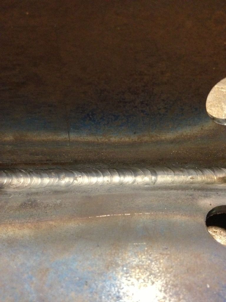
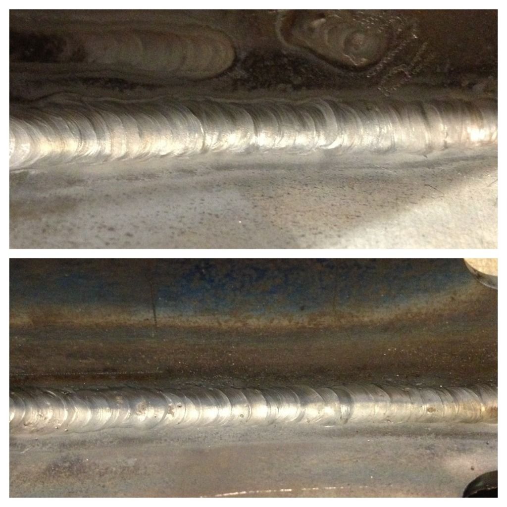
Ok, got some work done on the neck.
Check the earlier pictures for how it started.
So i added on to my jig something to hold the neck sturdy. For anyone wanting to do this, a taper lock 1008 1.0 bushing like this
will slide over a 1" shaft and perfectly center it in the neck like this:
If you weld on the bushings they will crack, though.
The above was used as leverage to bend the neck and also to ensure it stayed straight. The square tube that’s been added onto the bottom of the jig served as a guide.
I don’t have a picture of the cuts before I bent it, but here is a picture of the cuts after i had bent the neck down.
(Bending the neck down alone with 2 gimpy legs was not easy, i wound up running a strap under the acorn table and pulling on it from the opposite side)
So then I beveled out the cuts and mig welded the shit out of it (3 passes). Did a little smoothing to the welds (it really didn’t need it but whatever). The neck is actually cast steel, not cast iron like i originally thought, so it mig welded great.
(sorry about the blurry pic)
So then I had a moment of panic. I threw the level on the outside of the neck and it was way off. Like 2 degrees off (which would have moved the tire about 2" off center. I almost lost my shit wondering how I could fuck up so bad when I took a break and realized that they must machine the neck once it’s welded onto the bike, so the outside is not parallel with the inside hole (which is what matters). So I grabbed a new 1" round and checked it for straightness (my last one bent while reefing on the neck) and installed it in the frame the opposite way like this, then hung a plumb line from it:
Looks good. I threw the angle finder on it but as you move the level around the OD of the pipe the angle changes so it’s pretty hard to tell what the angle is…
But the plumb line isn’t hard to read. Sits right in the middle of the backbone.
I realize the backbone isn’t the BEST judge, but it’s a good second check!
 REALLY wanted to put them on the CB550…


