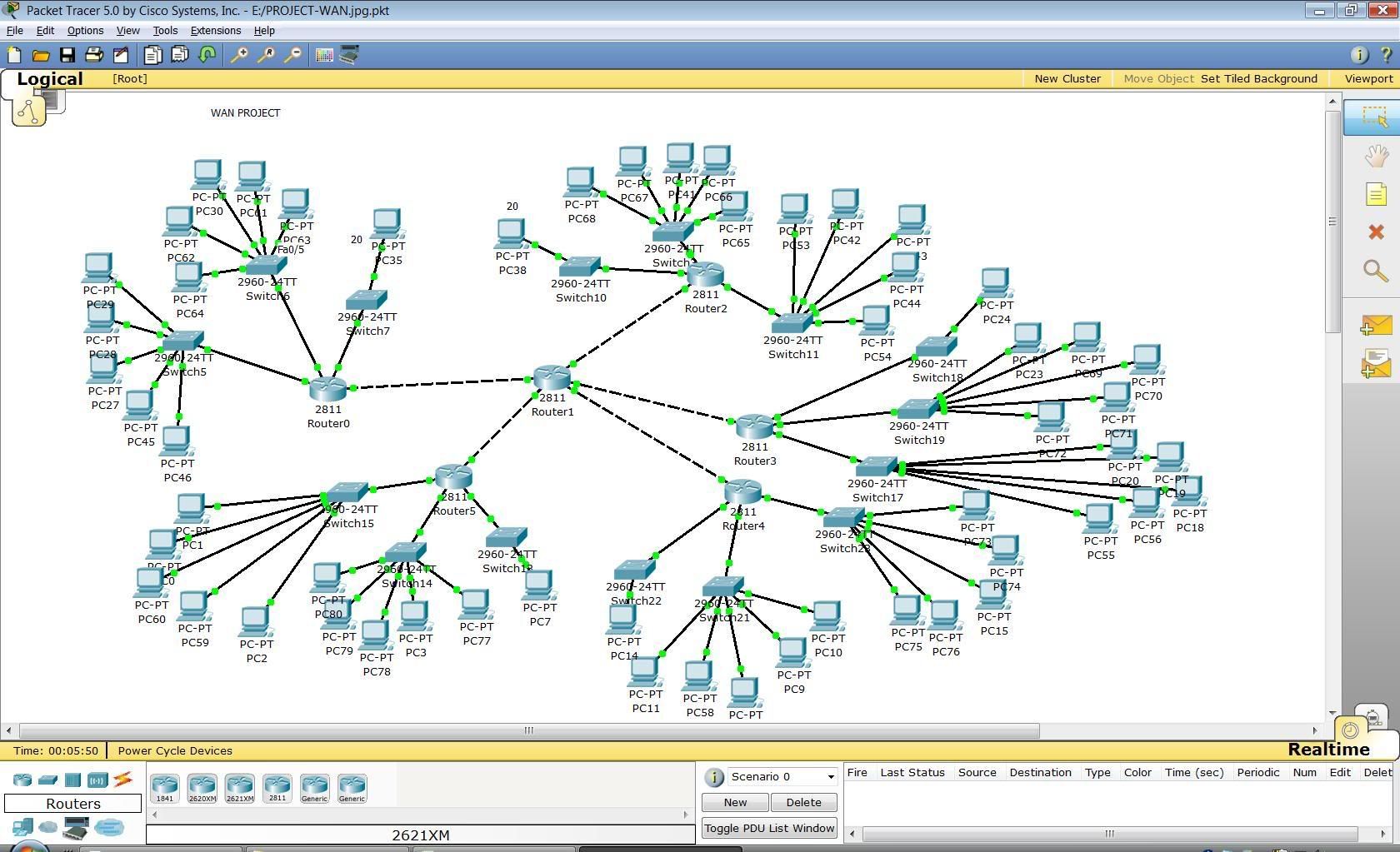
I need an example of a network topology/floorplan to help me with a school project. I need to show wiring, routers etc. I dont need to show any clients.
google search come up with anything? Looking for a good visio diagram to go along with an office floorplan?
how detailed are you looking? router settings, ports, all cabling, actual photos?
^ not quite like that. I have a birds eye view of an office building with 20 offices, 12 servers, lunchroom etc. I am to wire the whole place into a LAN and then show what equipment I would by (what model routers, switches, how much cable, etc.)
Having trouble with google. No actual photos. Basically if you were given a diagram of a bulding and your boss told you to wire it and show me your proposal in the morning.
Do something basic. Make it an office of 10 cubes. Each cube should get two RJ-45 connections with CAT5E through the wall, one for VoIP phone and one for the workstation.
Run all cables to the rack in an air conditioned, power-separated server/rack room. Patch panels of course to terminate all of the wall connections.
With only 20 workstations, a 48-port Layer 3 switch would be great. If the business is cheap, a regular layer 2 switch will be fine as well but not as easy to manage/maintain in emergency situations. You’ll probably have more than 20 workstations in the office though, as there is probably reception, extra cubes for visitors, conference room table and don’t forget about the network printers!
For the project I recommend just suggesting Dell products for the workstations bundles, network printers, desktop printers and the servers. Easy to research and find a simple solution for the project.
For the VoIP you’ll also have a phone system in that room seperate from the workstation network.
I’m just going on and on… I’m not going to draw it all up for you… 
Are you having problems because you’ve never seen an office set up and are not sure what to do at all? Are you familiar with a patch panel, switches, routers, etc. at all?
Post up the building layout he gave, perhaps someone will have some fun and do it for you. 
The red circle is the server room. The rest of the rooms can be anything I want.
I appreciate you replies. And if my teacher reads this thread I would like to say that I am not cheating. Just asking for advice VIA internet. I could wing it like this in real life couldnt I?
I just did a whole project like that for my final college class. Here was our office layout (no wiring) you can however bring it into visio and wire it in there. I put a list together for all the things we used…if you want to look at it let me know.

lol I will find something after I wake up.
First of all no one does two runs to cubes anymore(at least with the model cisco, shortel and many other voip solutions suggest)…Most networks are setup with one run to each desk cat5e/cat6…The ethernet runs into the phone and then into a computer…The VoIP phones are VLANed out…
Shouldn’t be hard just decide if the phones are PoE or not…48 port patch panel in server room…1 big switch or two if you are building a redundant network…
Are they concerned about spanning tree or actual configuration?
make sure you don’t exceed the 328ft if you do a run to the last room…If this is the case you could add an extra wiring closet some where in the middle and run two(for bonding or fail over) cat5e cables and bond them(etherchannel on a cisco) or if you have a lot of EMI use fiber…
Tell that to Homeland Security. ![]()
We are moving to a new location and STILL getting two data drops. LOL
They do it to keep the phone system and data network seperate. They don’t like to configure VLANS I guess, or perhaps the network people would rather spend more money to make it “simpler” and “easier to manage.”
As for the map, the last room on the right is a trick. You will definitely need to make that little closet in the bottom right a 2nd switch room which needs to be connected to the main server room.
Use some fiber to connect the two cisco switches, easy. 
Do you have a budget for equipment? Do you need to provide equipment names, etc?
Or is this simply need to be a visio drawing with an Excel spreadsheet to show port designation.
I’d fucking HOPE NOT if you were getting paid.
No budget but and yes I need to provide equipment name. And yes and yes.
I don’t know if this will help at all, but it’s a product list I made of stuff that we considered using for a real life simulation. If you click on the bookmarks on the left side everything is categorized for easy browsing.
never worked in a run-of-the-mill IT shop huh? lol
Haha is this for a MIS class at UB?
My friend used a diagram I had for a client in Phili for his network layout. I thought it was a dumb idea for a project as it didn’t really teach much.
I’d show you guys my office network, but then I’d have to kill you. Haha just kidding…
I’m running a cisco 2811 perimeter router into a 3550-12T gigabit layer 3 router. That then splits off into several linksys layer 2 managed switches for different vlans and one is PoE for voip phones. I have about 5-6 cat5e runs into each office, so my entire network is gigE.
I used to be a network and security consultant for IBM Global Services.
