Project: SteeZee - 1973 Datsun 240Z LQ9 V8 Build

So probably one of my more productive days woohoo!

Did the passenger engine bay same as the drivers so no real process pics required:

Then I did a 1x3x.120 up the footwell at a 60* angle and all the way along the floor. The floor was bowed from welding the whole panel in but with a bit of planning and a bit of weight on it - it squared up to 0.1 degree side to side and 0.2 end to end relative to pinch weld and 0.6 degree relative to the engine bay rail - not too bad. I capped the top of the 60* piece so it’s nice and flush but I might add a small drain hole for condensate inside the rails.

Nice and square :smiley:

Ill match the other side up next weekend hopefully. Then tie both into rear subframe, add the 20* pieces connecting the engine frame rail with the floor rail and get some wheels bolted up and set on em!

definetely sexy

Had some time today to get some done on the Z :smiley:

Matched the passenger footwell, floor rail and footwell rail to the drivers. Still have to clean up a bit of the weld on the joint there but it turned out alright.

Made the mount for the front of my rear subframe.


I have to find out if the subframe fastener can stick through the mount plate for my cage main hoop. If it can’t, I have to inset a nut inside of the 1x3. Anyone know if I can?

Amazing work man! can’t wait to see some more!

Thanks Kouki!

Same old game - days off getting farther apart and I’m going to McMaster part time to finish my B.Tech.

Updated the Solidworks model with cage:

Plated the rear strut tower tops and fitted the rear tower member of the cage. Also cut out the rear floor to the frame rails so I can start on fuel cell frame.

Hit up BendTech for the main hoop - thanks Joe!

Cut the main hoop base at ~9 degree angle towards the rear so it sits flush at base when hoop was in place.

Didn’t wanna waste $100 on a lift plate - cut piece of scrap 1/4"x6"x18.5" plate, drilled 10 holes, zipped two 1" pieces of scrap pipe, ground flats on each of them to sit square and just need to weld er up. $2 lift plate (cost of fasteners haha) :smiley:


Thanks for the update

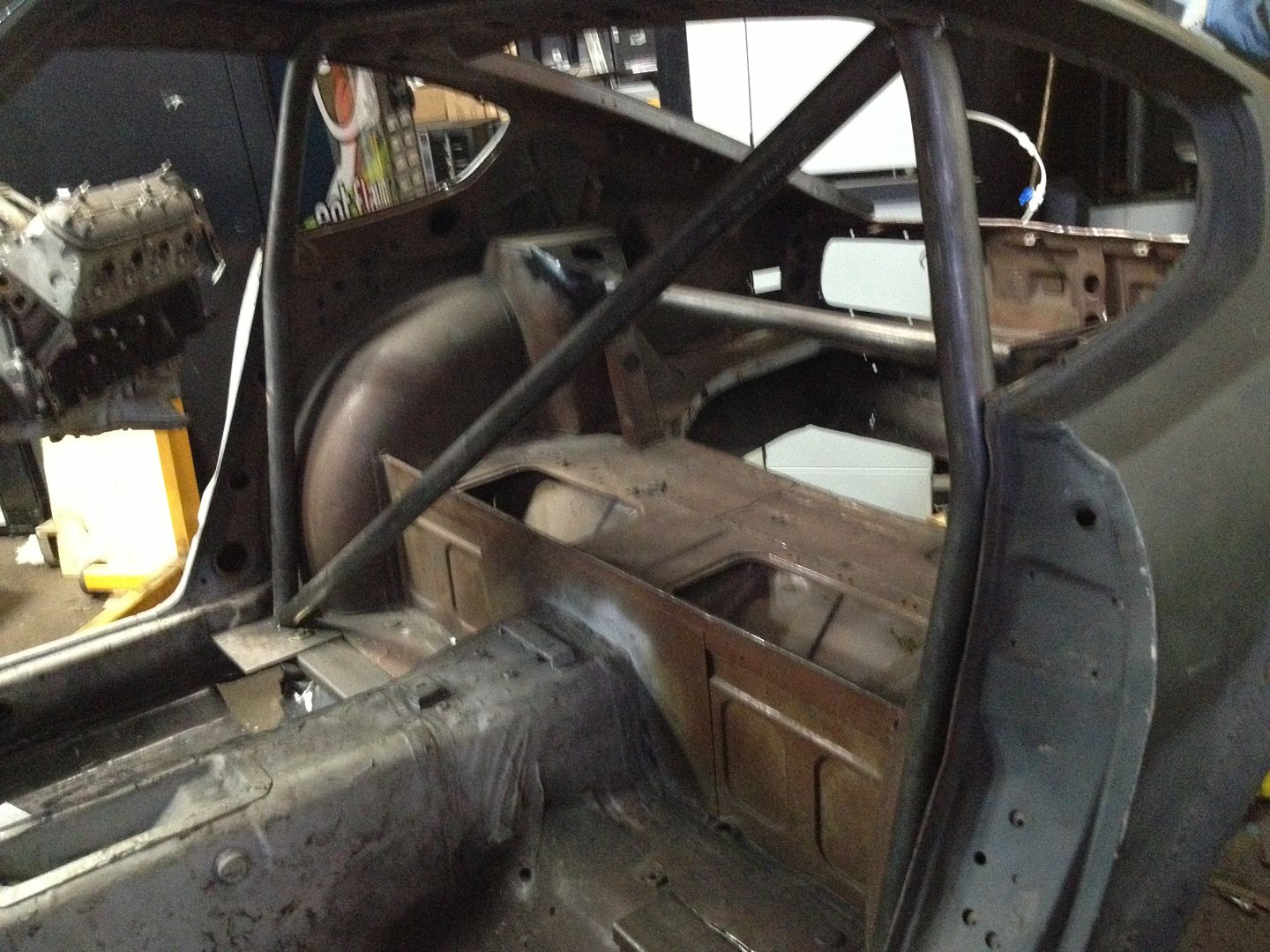
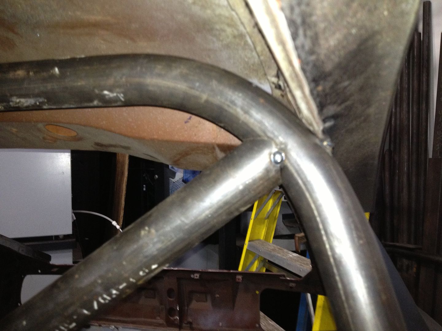
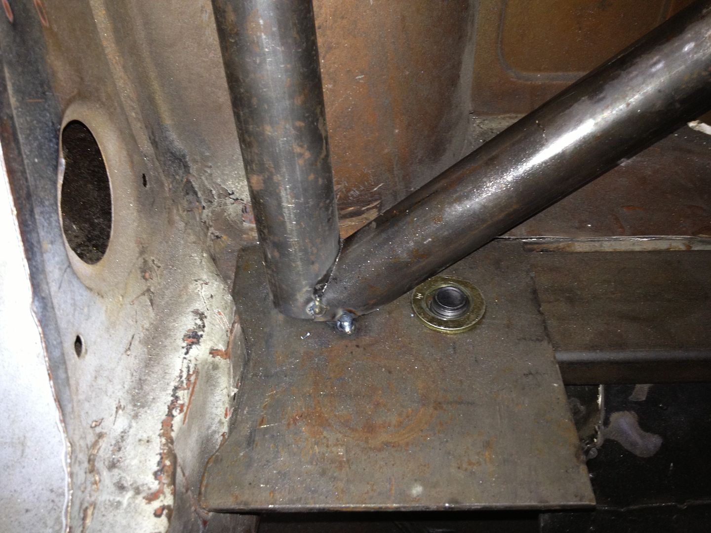
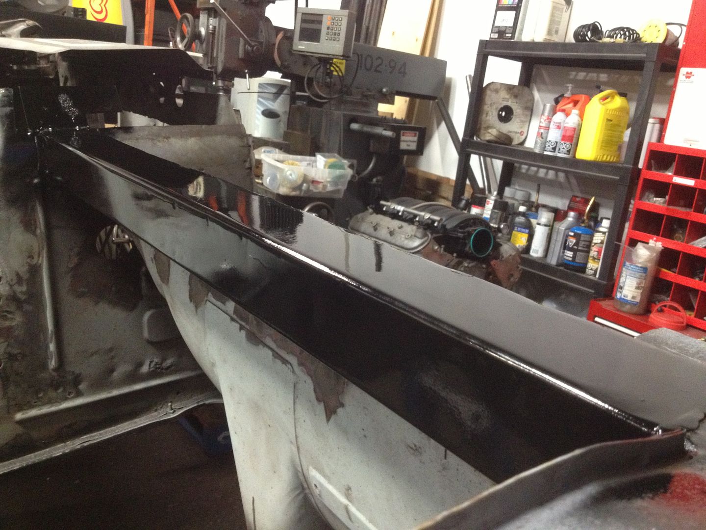
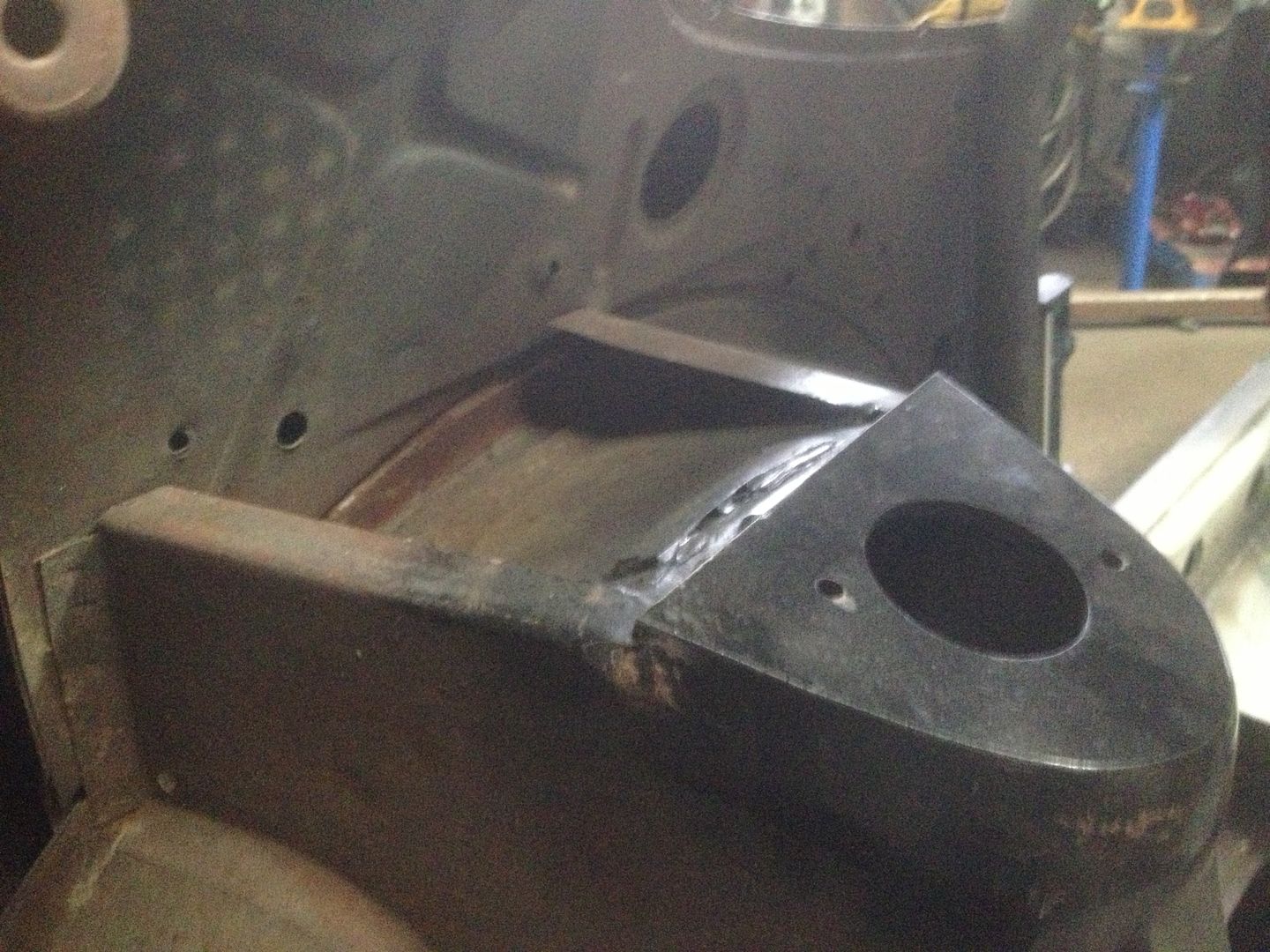
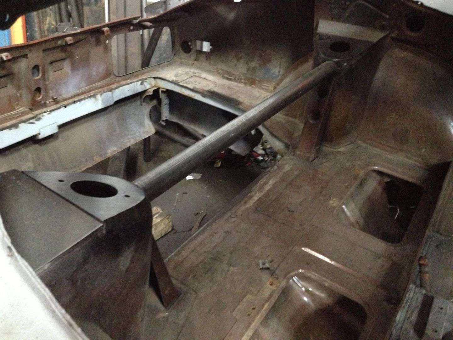
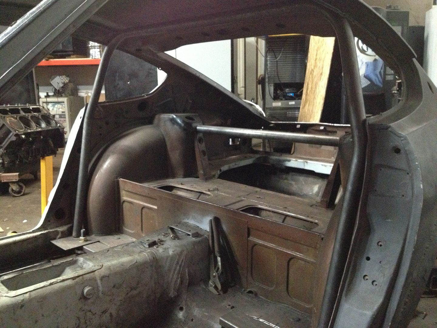
Hit up the shop today - got the main diagonal in. Before someone mentions it, I plan on taking the tacks off and cleaning up the weld joints next weekend before continuing the rest of the cage - I just didn’t have any emery cloth today.

http://i243.photobucket.com/albums/ff286/Aaj2k5/CF6A278D-1EAE-4097-8F6B-6DB7882495B3-2637-0000042257B4E47F_zpsea5e9d9b.jpg

http://i243.photobucket.com/albums/ff286/Aaj2k5/A85DDD1E-35C1-4CF1-BB17-311A21B2219B-2637-000004225FA47BFC_zps78f75a22.jpg

http://i243.photobucket.com/albums/ff286/Aaj2k5/2F00C803-B23D-4D9A-8123-7B8E59FFDB51-2637-0000042267771566_zpsfaa65ca4.jpg

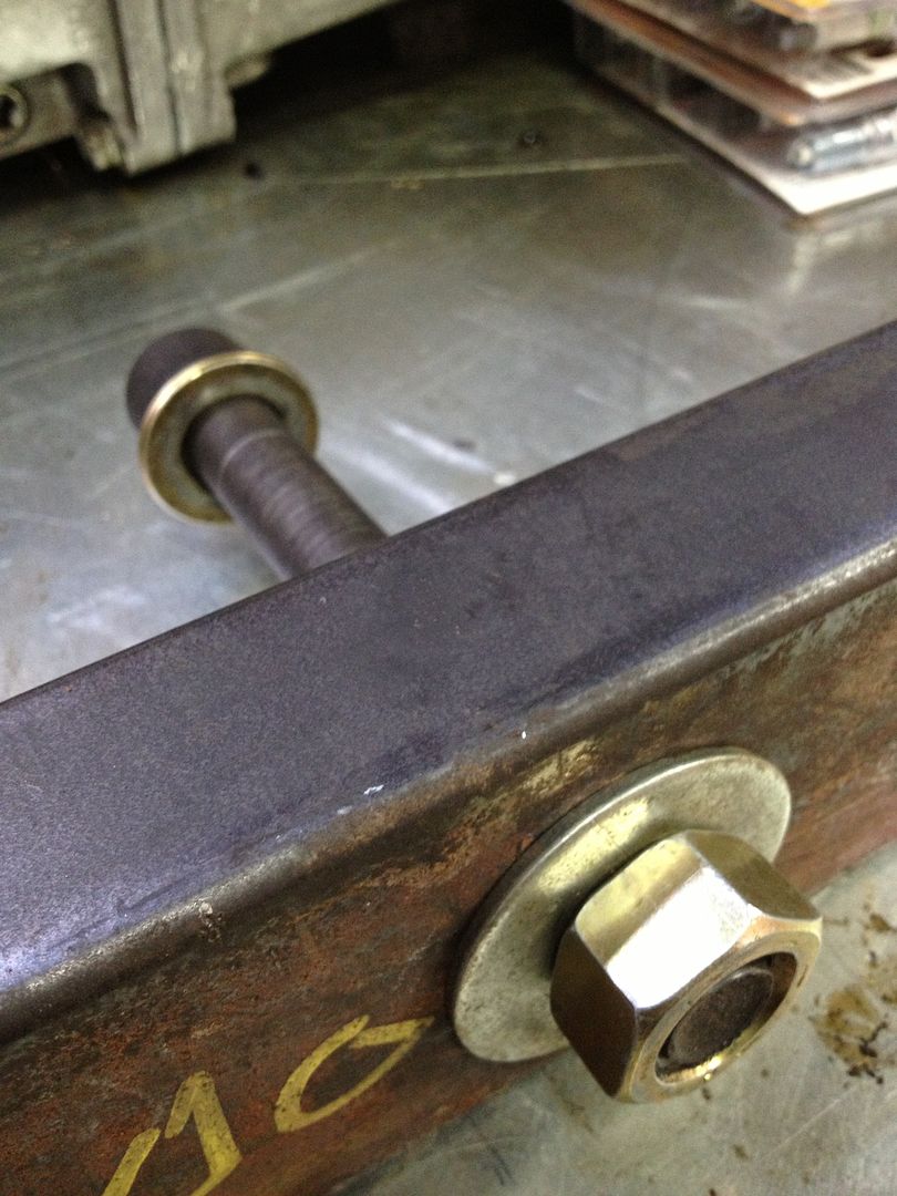
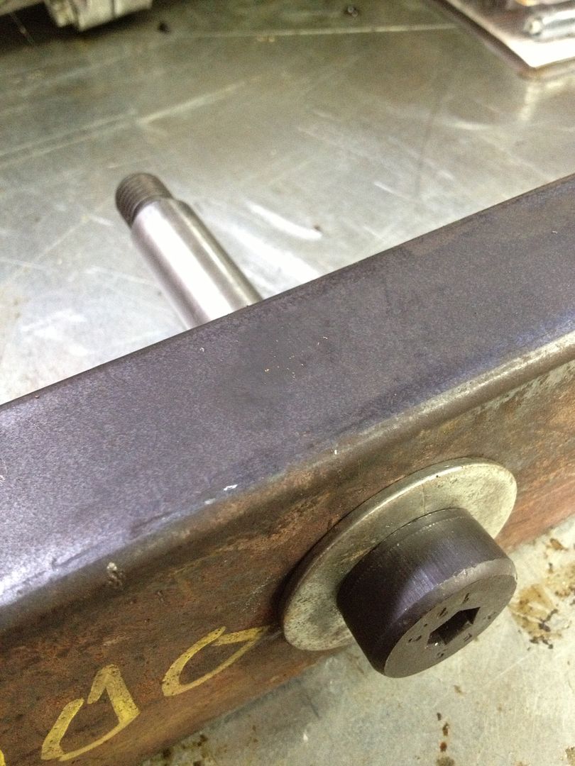
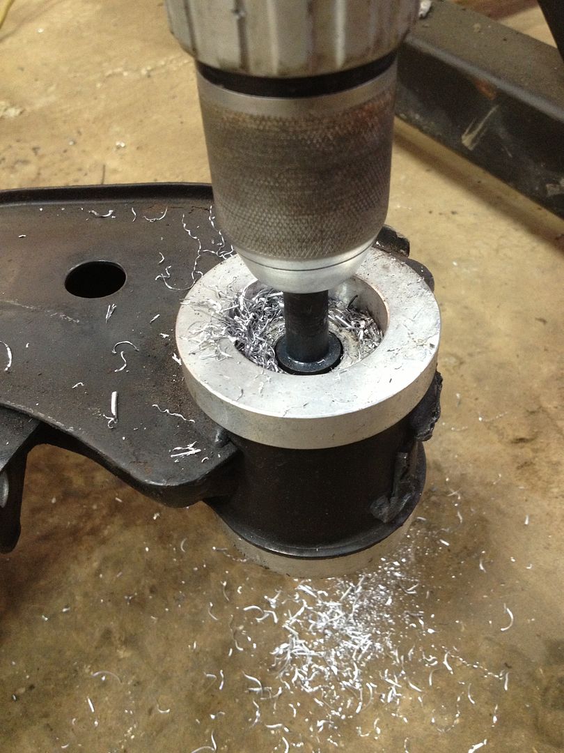
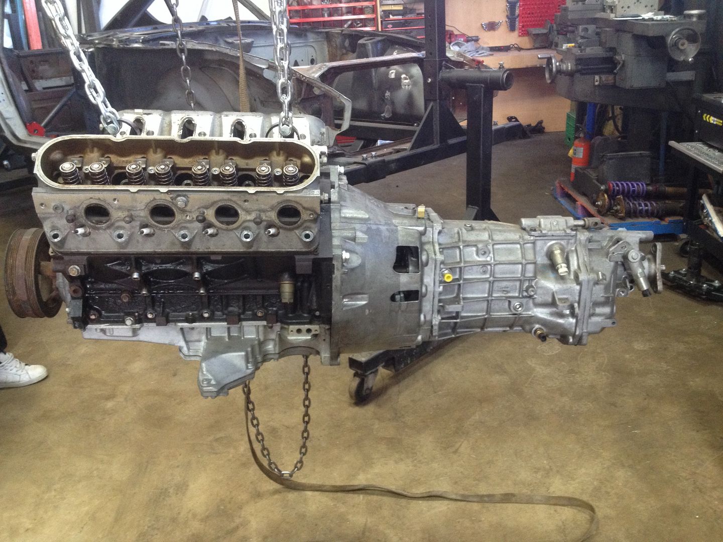
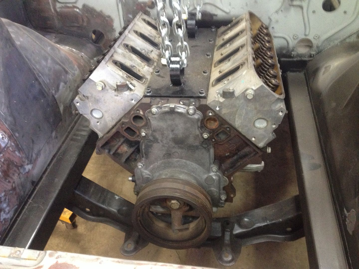
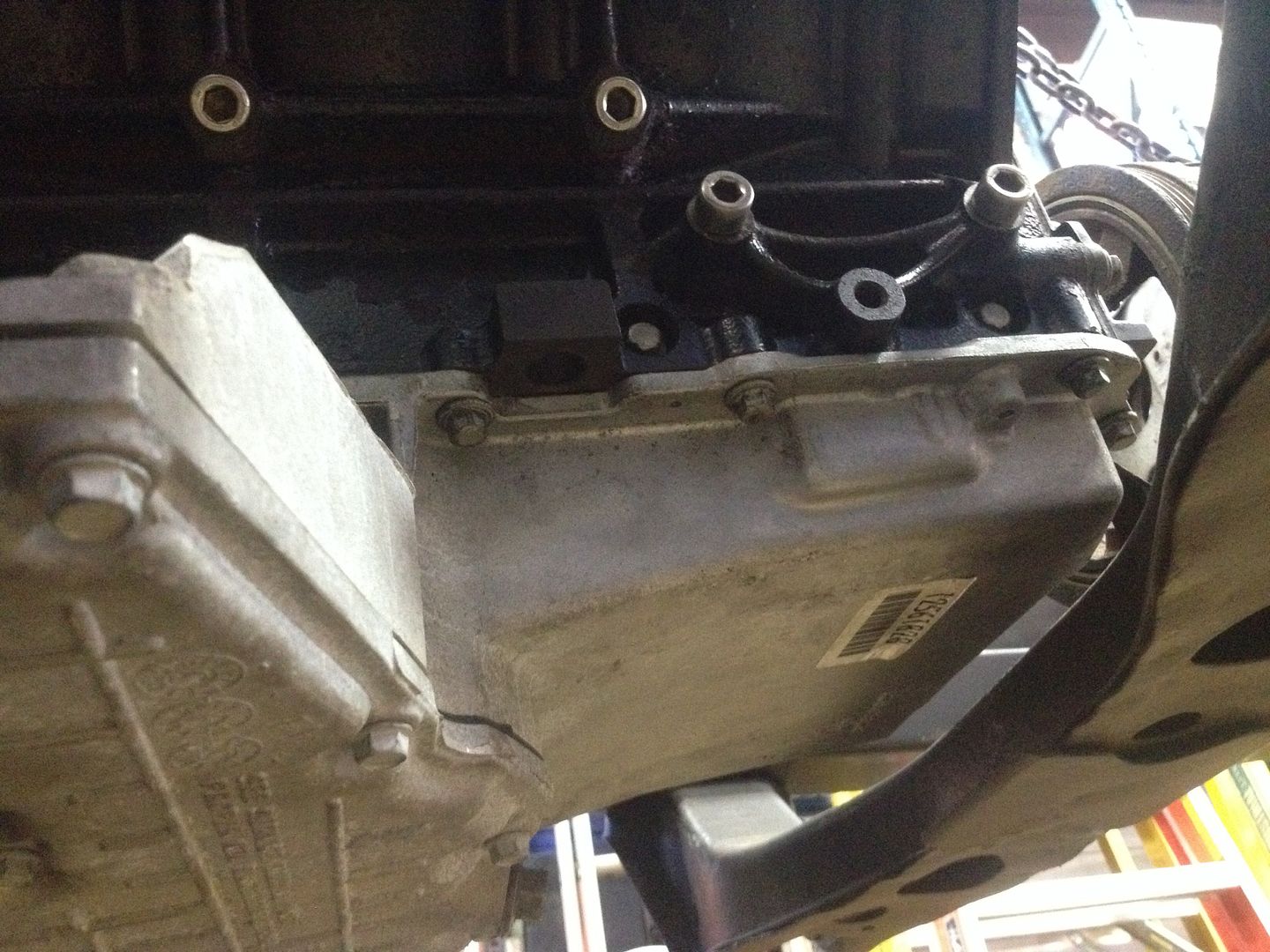
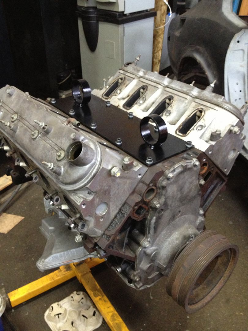
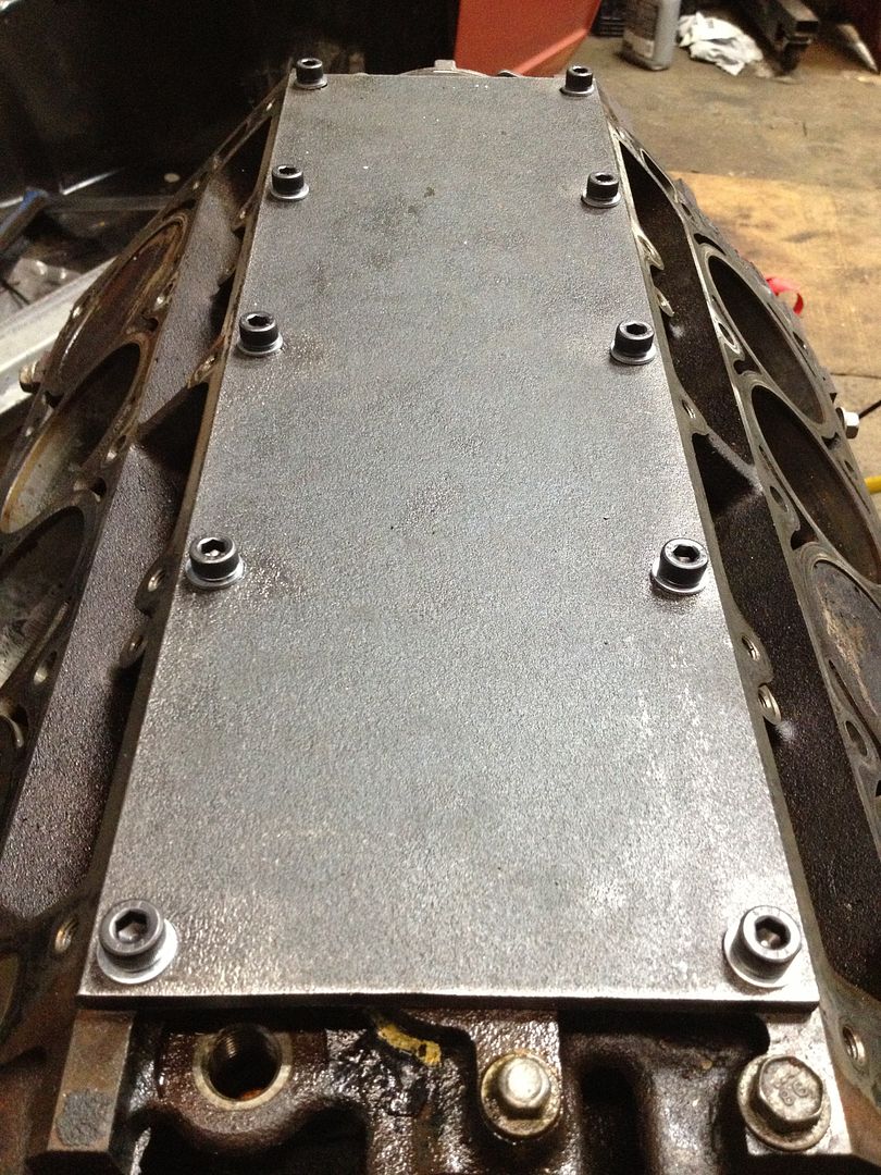
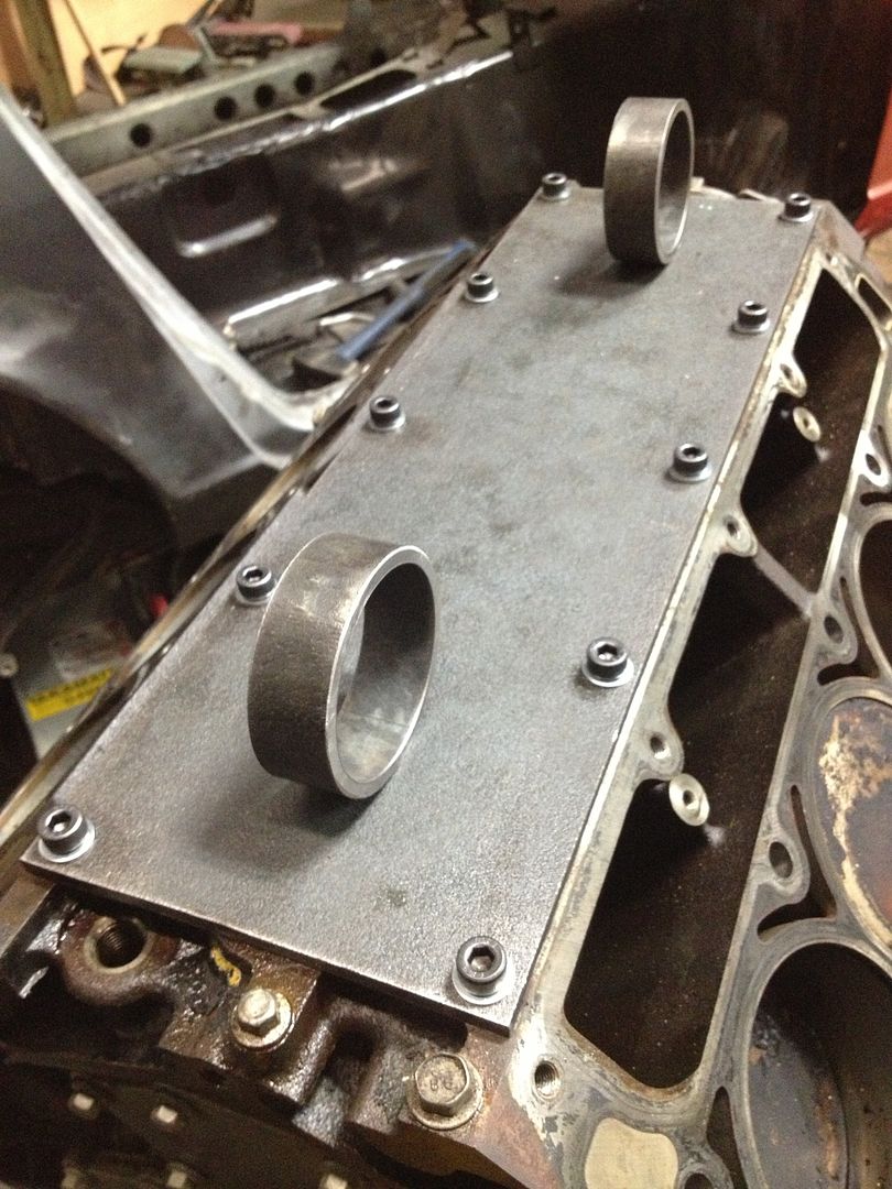
Also finished up that lift plate. Buying some engine goodies this week hopefully come in for the weekend.

http://i243.photobucket.com/albums/ff286/Aaj2k5/812233A1-0029-4ADC-BBCD-2935765B0B4E-2637-00000422B8A6E555_zpsac741eb6.jpg

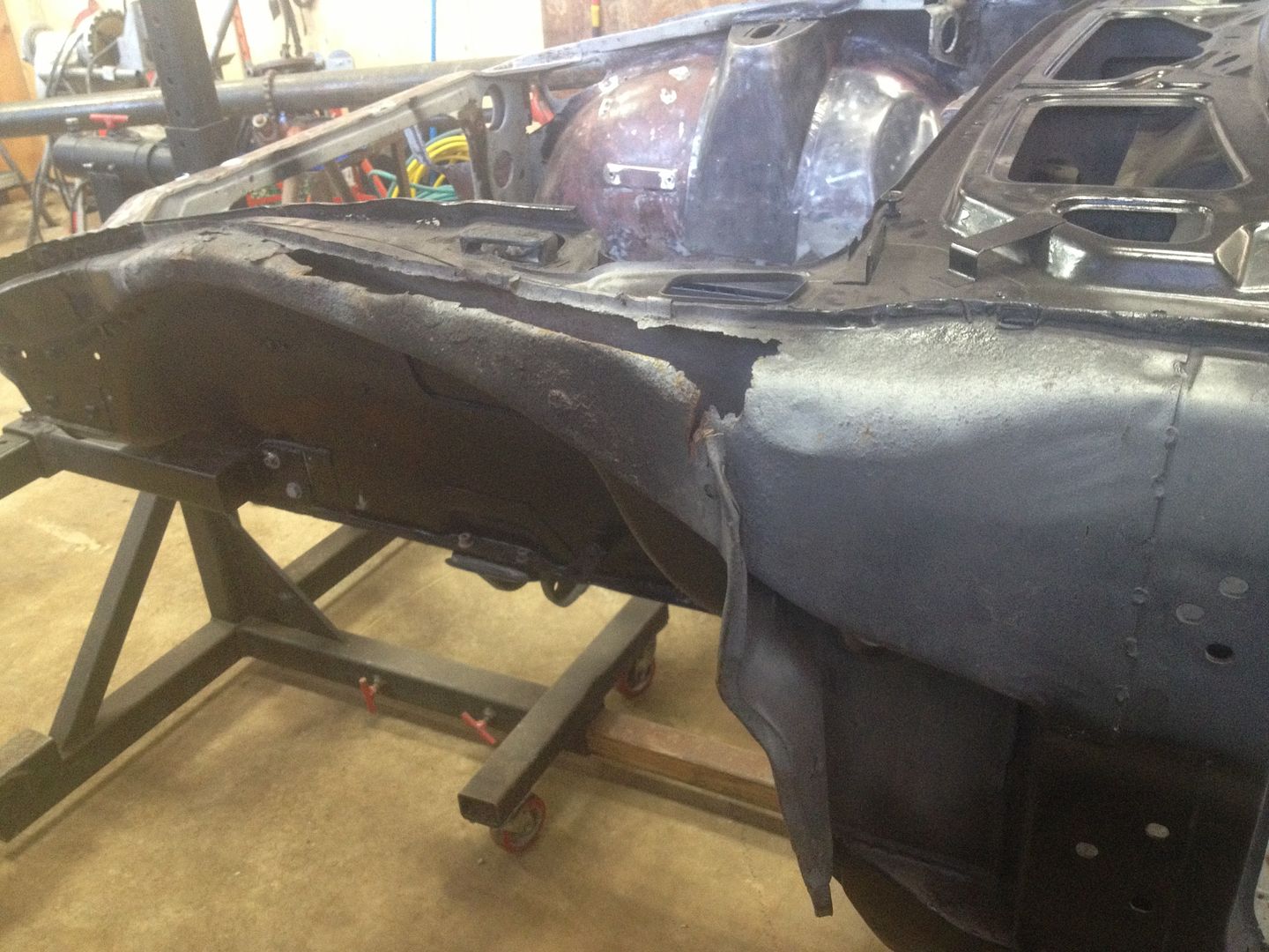
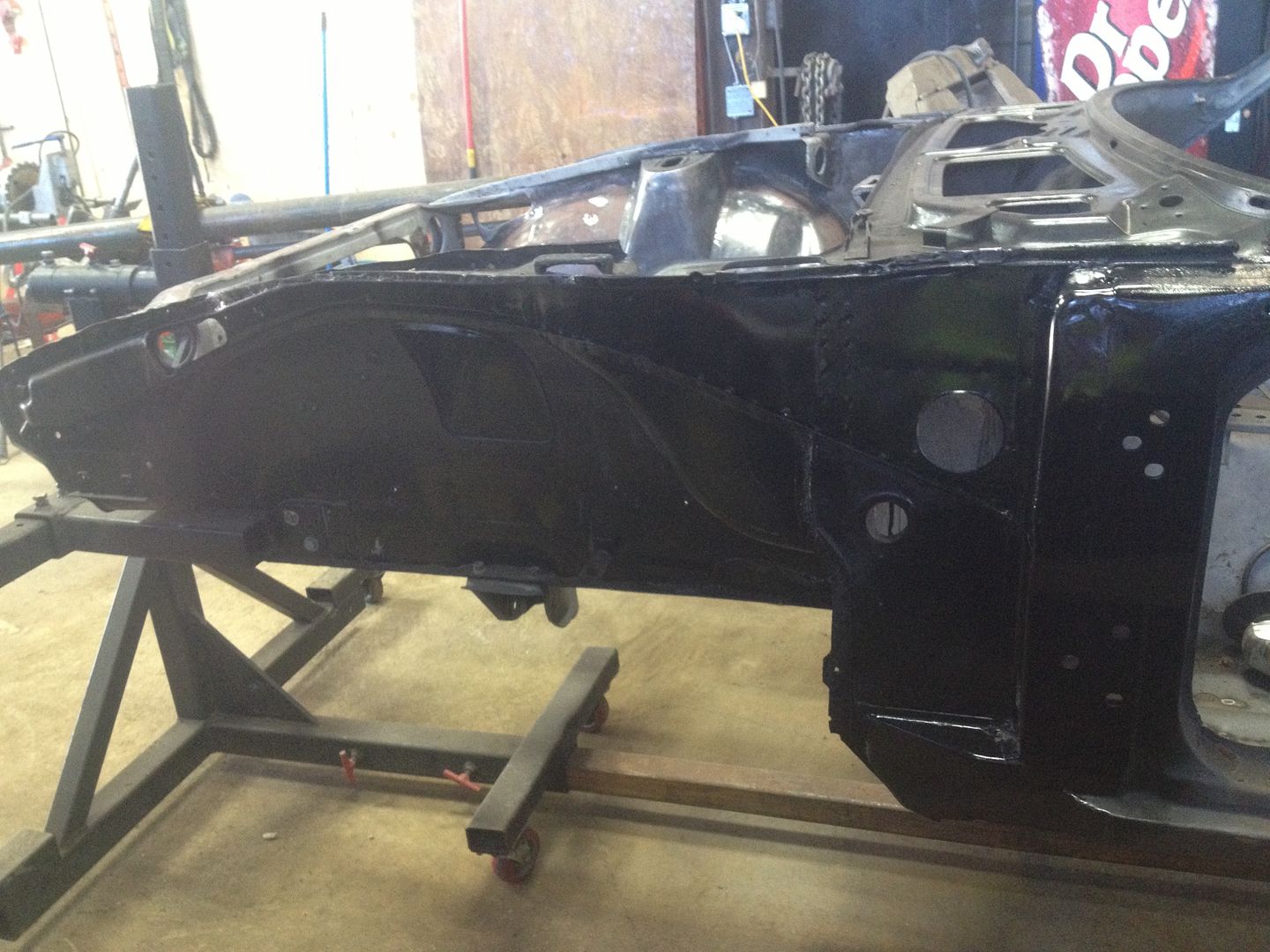
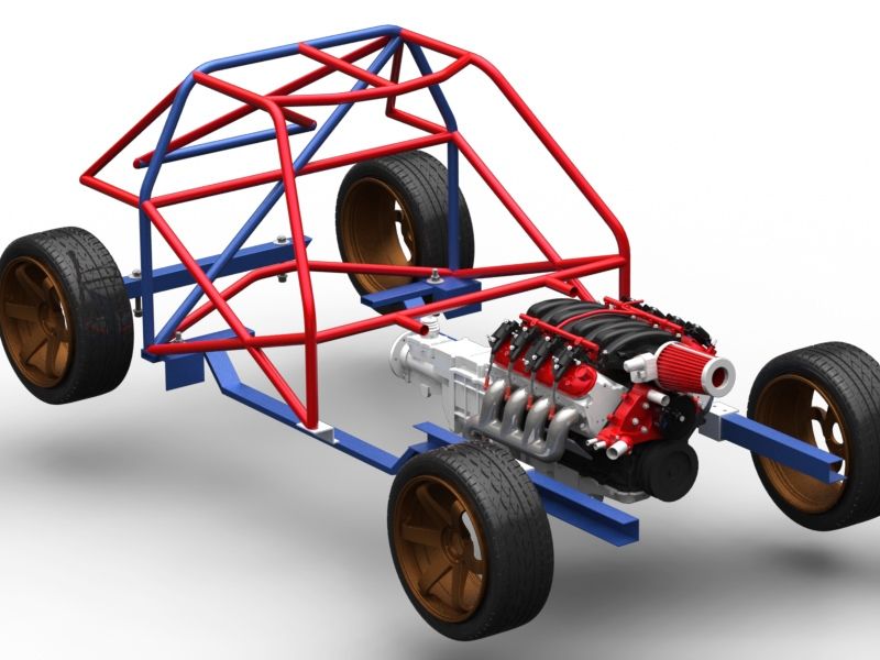
I’ve decided on making a tubular front subframe - anyone have any good reference examples? It will hold my engine mounts, steering rack and control arms.

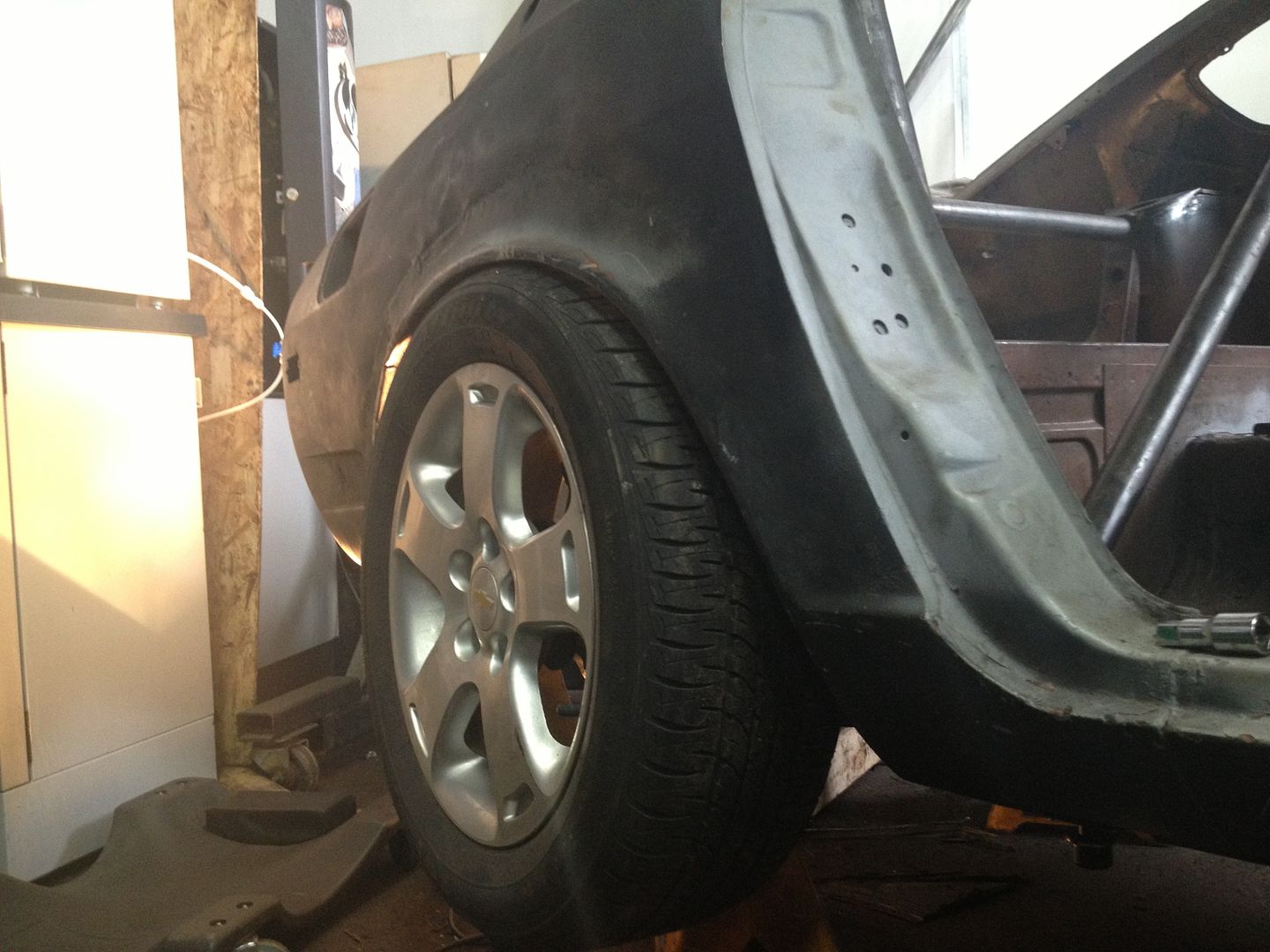
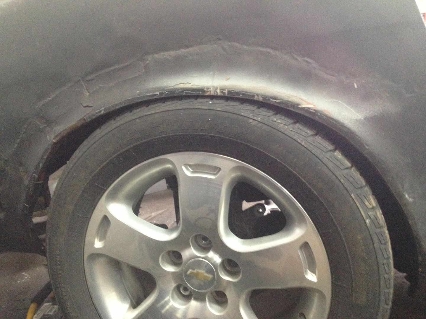
Obviously not the wheels I will be running, however these 205/60/R16 have the exact same OD as the 275/40/R17 I have at the shop. Someday will be 315/35/R17, but I’ll run the Yokohama 275’s I already have first.

http://i243.photobucket.com/albums/ff286/Aaj2k5/5CEC0A0B-E23B-415B-80D0-D98AAF1B78E6-688-0000013976944E05_zpsf95f410f.jpg

http://i243.photobucket.com/albums/ff286/Aaj2k5/7B86E0B2-AC8F-4C60-ABBD-8ED173237A67-688-000001387A13E94A_zps5b1085b0.jpg

http://i243.photobucket.com/albums/ff286/Aaj2k5/02821528-056F-4C72-A724-5751CABDE399-688-0000013884DC4097_zps02cce832.jpg

http://i243.photobucket.com/albums/ff286/Aaj2k5/FF637A17-D3DD-4A4E-BFEB-452661BBC547-688-0000013892697247_zps694eef87.jpg

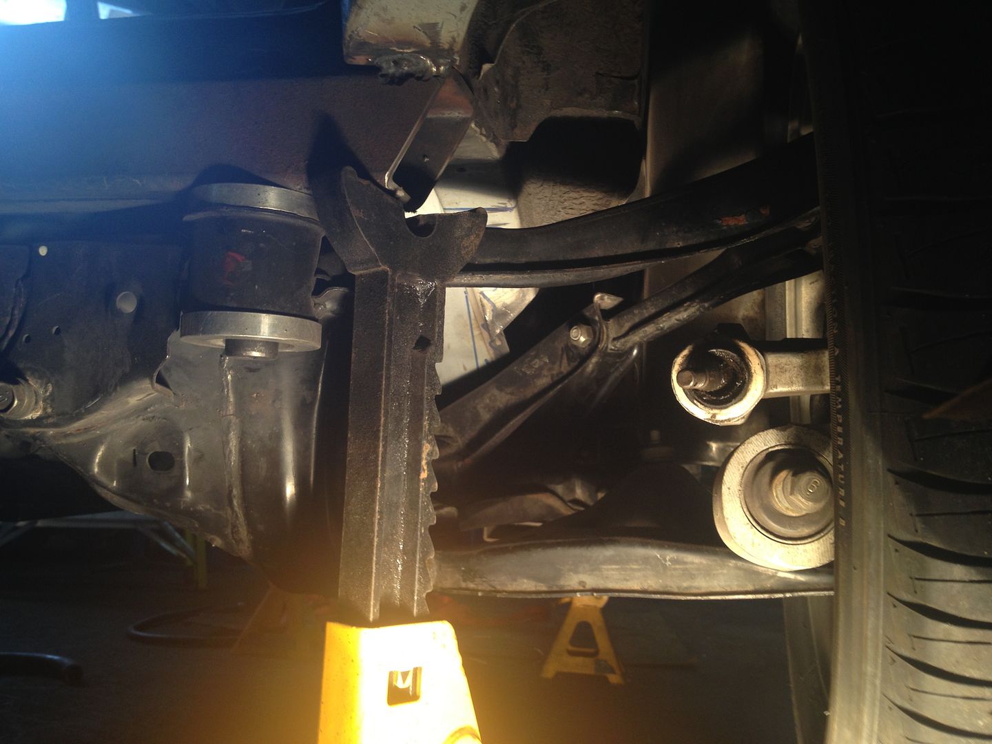
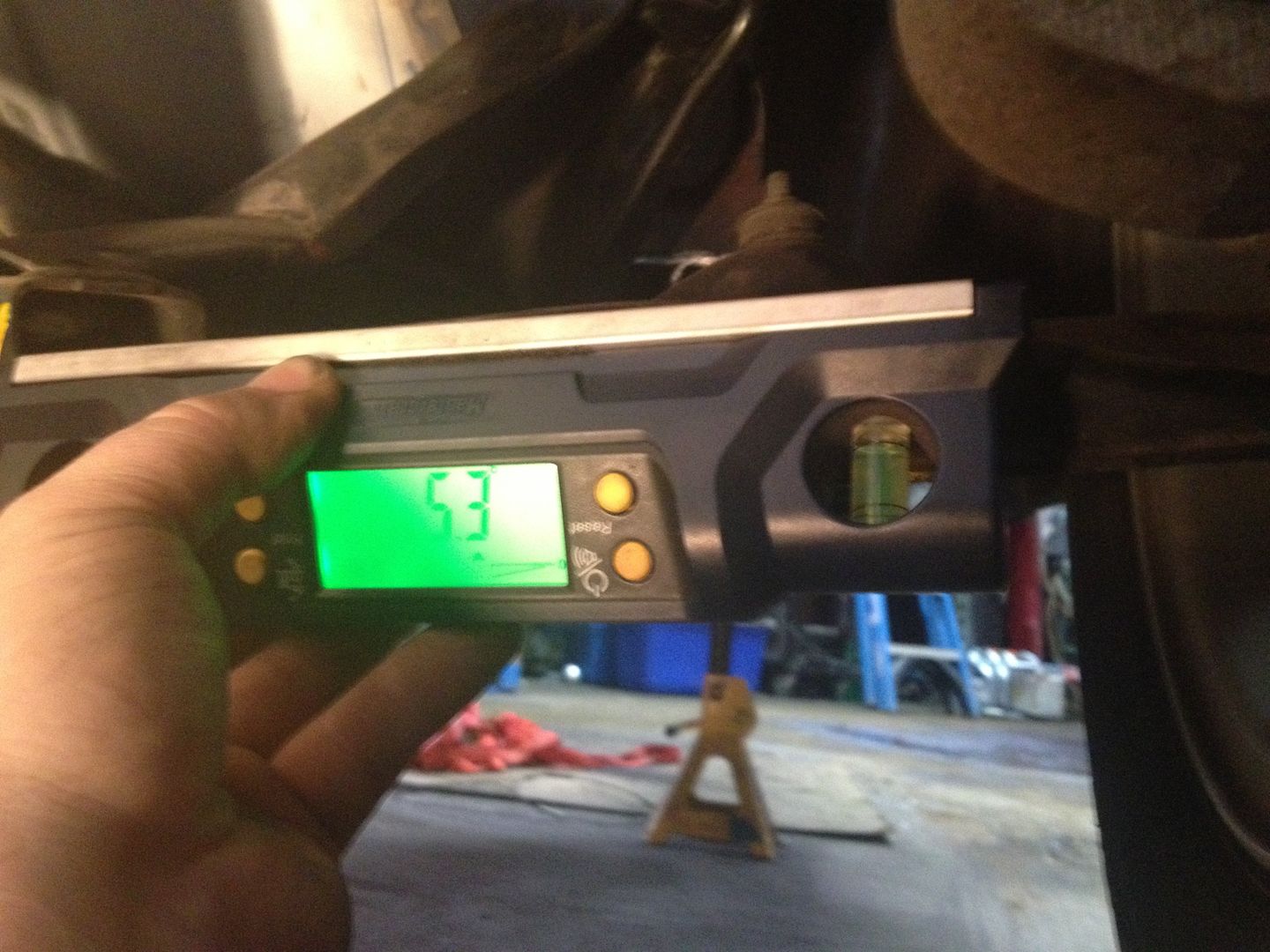
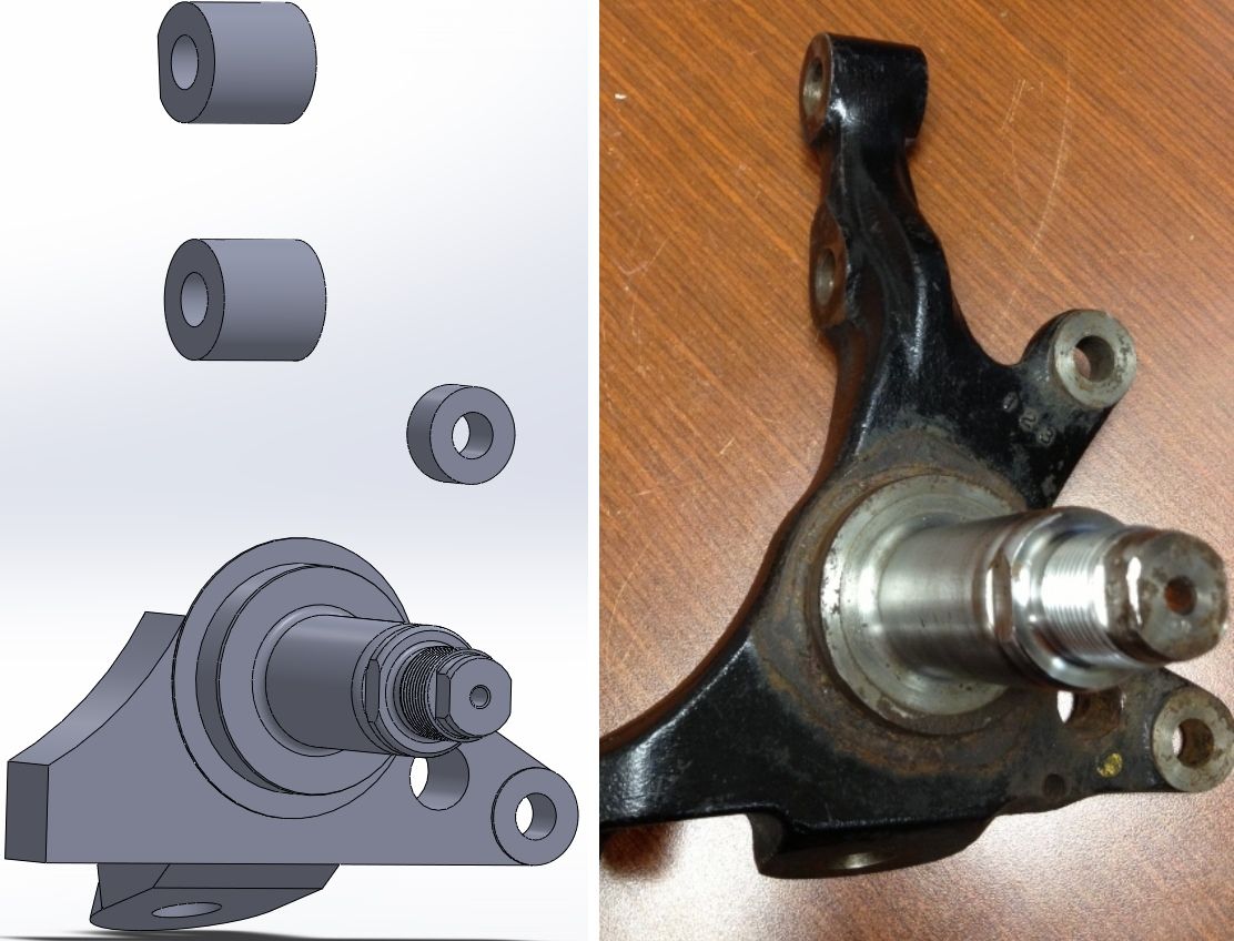
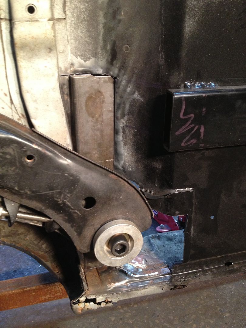
The forward rear control arm mount is at 0 degrees centre of mount pivot to the centre of the balljoint at the ride height shown. This leaves 3.5 inches of wheel travel upwards from ride height once I cut out the wheel well and run extra wide ZG flares

The rearward rear control arm mount is at ~5 degrees from centre of mount pivot to centre of balljoint at the ride height shown.

Suspension experts: Is 3.5" enough wheel travel or am I leaving too much or too little of a gap before hitting tire into wheel well? The optimum parallel RLCA - is this to the front mount or the rear mount of the RLCA?

All arms will be adjustable, but if I have to move my subframe mount up - now would be the time to do it.

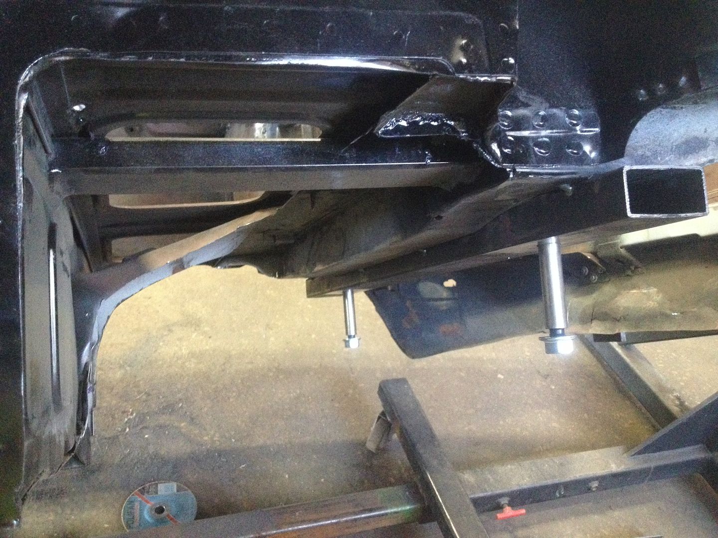
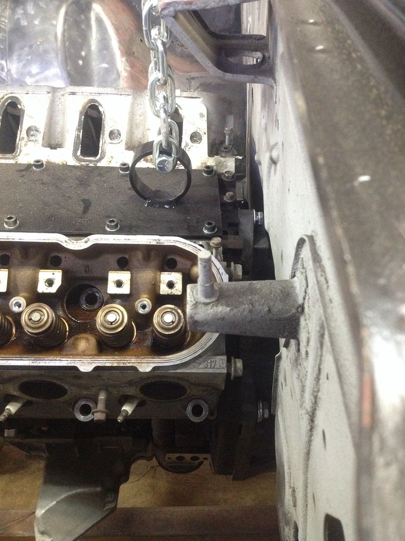
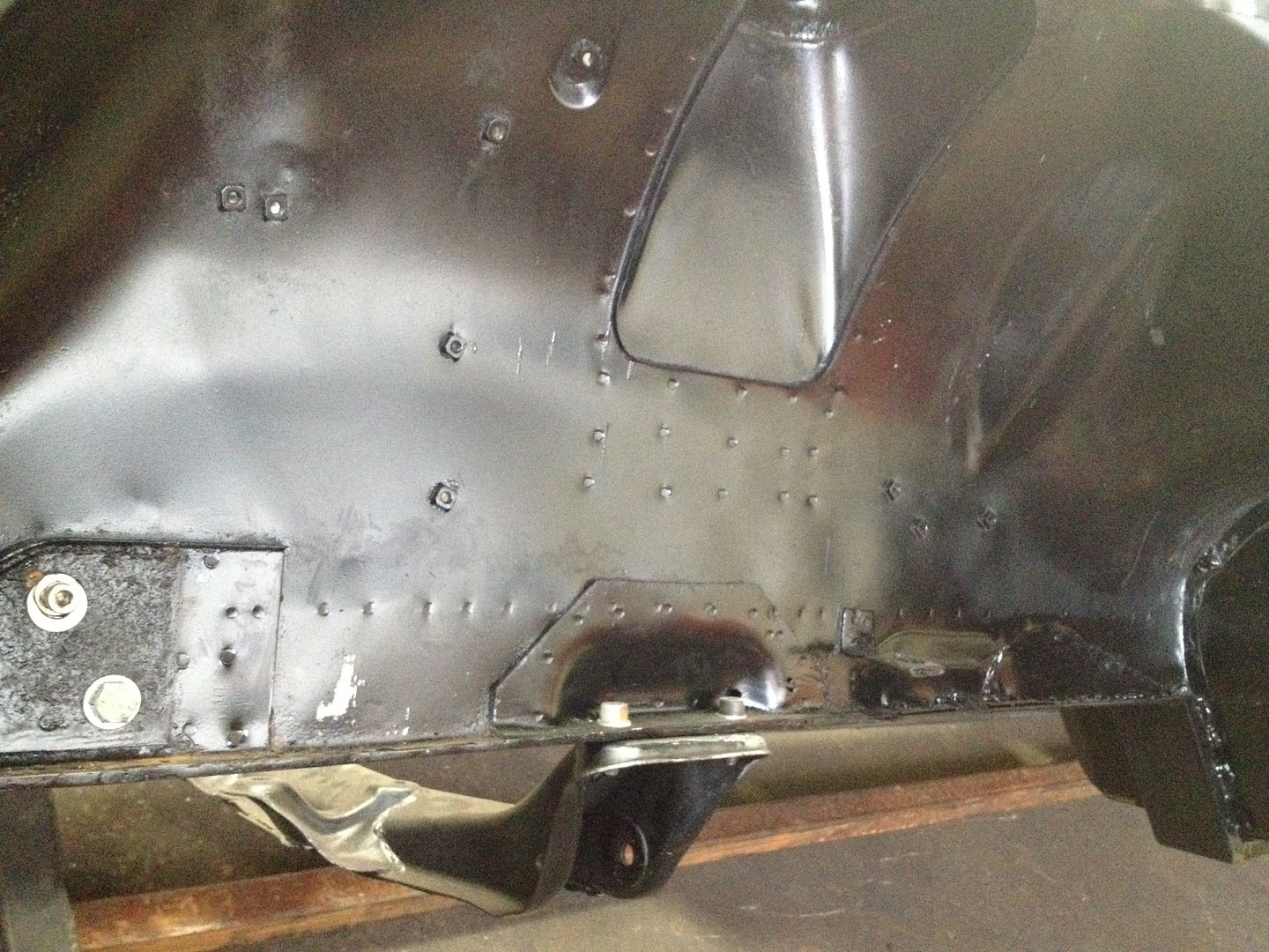
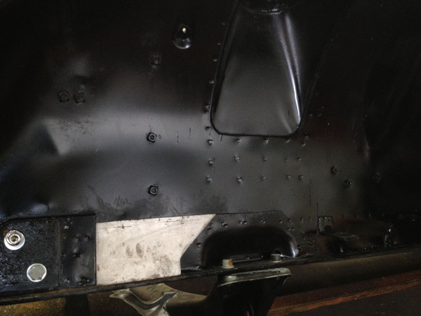
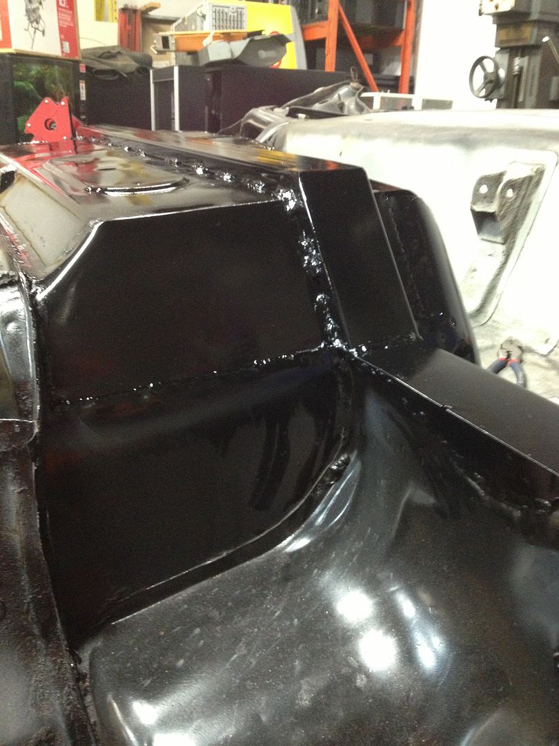
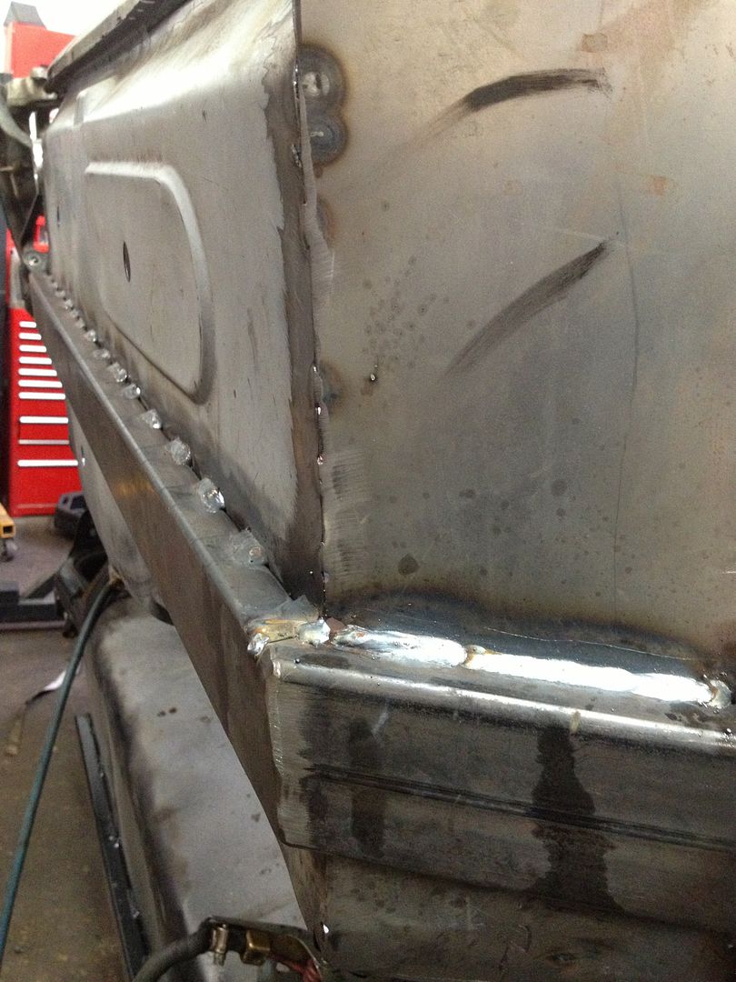
Also, made these braces up - will make the same for the other side of the engine mount bracket all the way to the firewall.

http://i243.photobucket.com/albums/ff286/Aaj2k5/8D16F45B-F6BA-4D58-93FC-096D46725C11-688-00000138543DFA65_zps23938dc0.jpg

http://i243.photobucket.com/albums/ff286/Aaj2k5/4BC6169A-609F-4FEC-8FED-E6C4962266FA-688-0000013860AAD0C0_zps3392a0e1.jpg

Factory 2012 Camaro driveshaft with the isolator placed where my transmission flange will be:

http://i243.photobucket.com/albums/ff286/Aaj2k5/8DB52125-B7C3-4256-AFD0-D0259094D9D6-688-00000138472B98F4_zps3b295edd.jpg

http://i243.photobucket.com/albums/ff286/Aaj2k5/7FBA31DB-DA66-44A6-B352-CA98DCB38325-688-000001383D624A5E_zpsd2081a4c.jpg

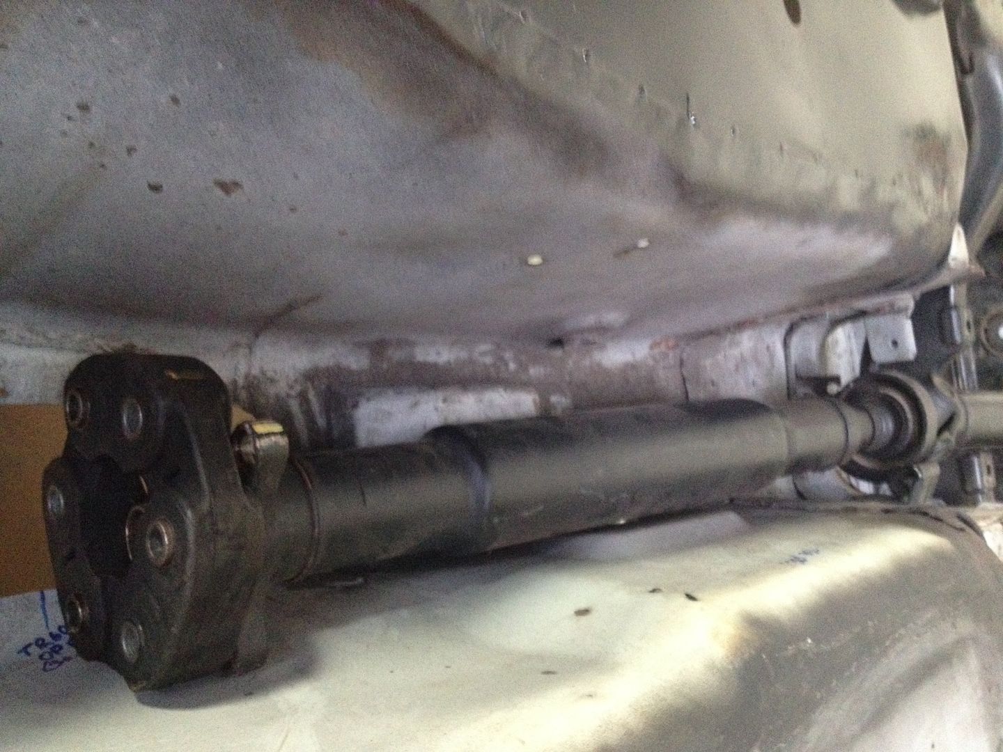
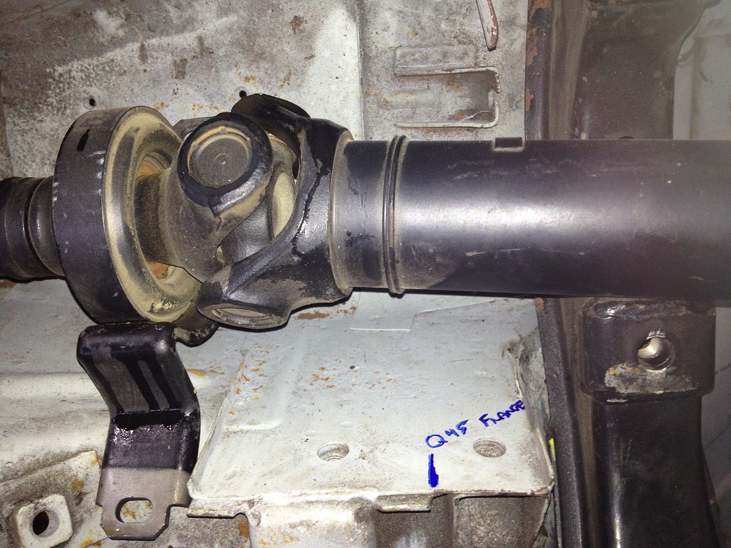
This means I can cut the second half of the camaro driveshaft off at roughly that weld line and weld a Q45 flange onto it for mating to my diff. I’ll have a U-Joint, Slip yoke as well as the rubber isolator at the transmission output shaft.

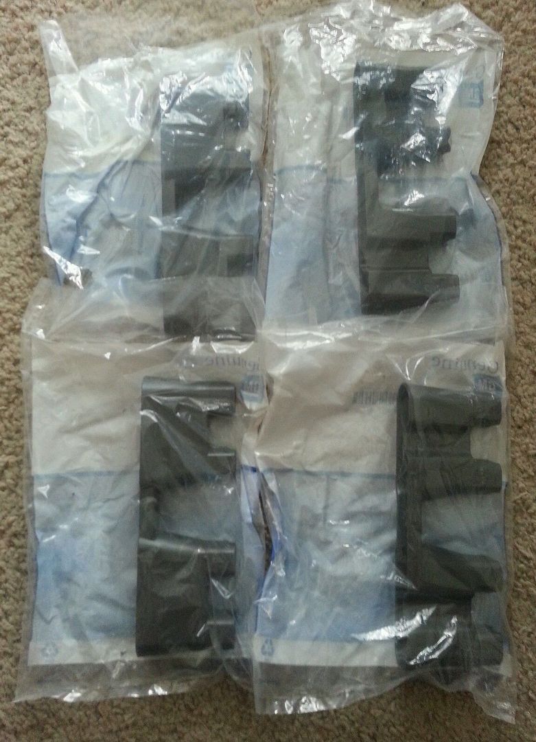
Picked up GM LS7 Lifters

http://i243.photobucket.com/albums/ff286/Aaj2k5/CB68n3wBWkKGrHqMOKj0EzlMlwGjYBNJegnb_12.jpg

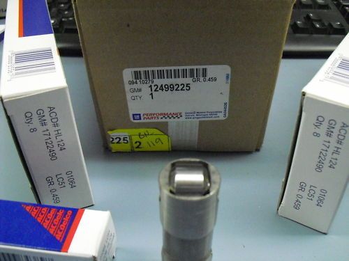
As well as GM LS2 Lifter Trays

http://i243.photobucket.com/albums/ff286/Aaj2k5/_57.jpg

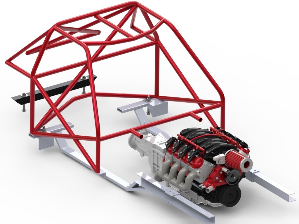
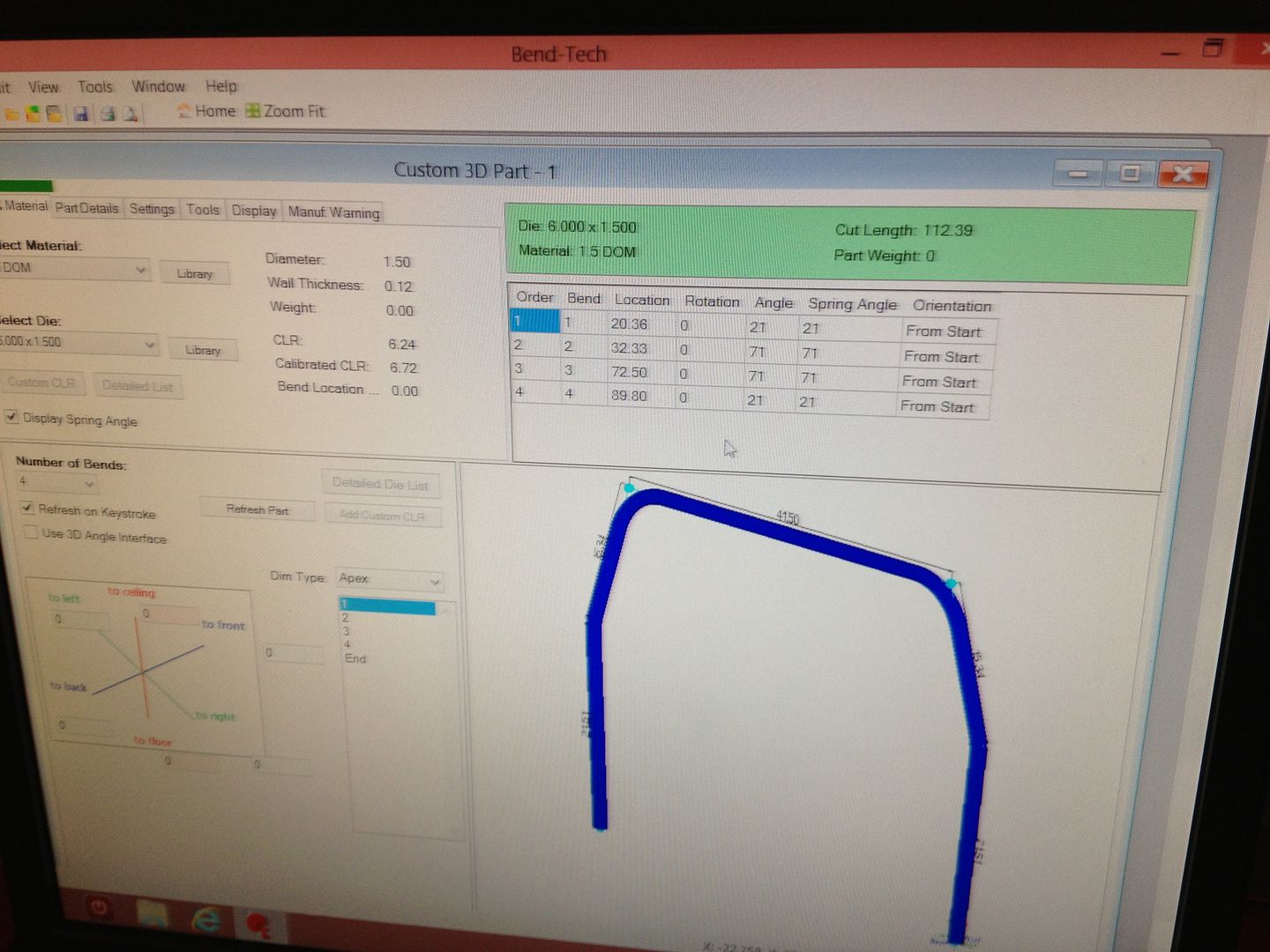
Everything in blue is done.

http://i243.photobucket.com/albums/ff286/Aaj2k5/E9F88077-0436-4793-9061-C0383FC50DA1-688-000001394EDAB954_zps78ebe263.jpg

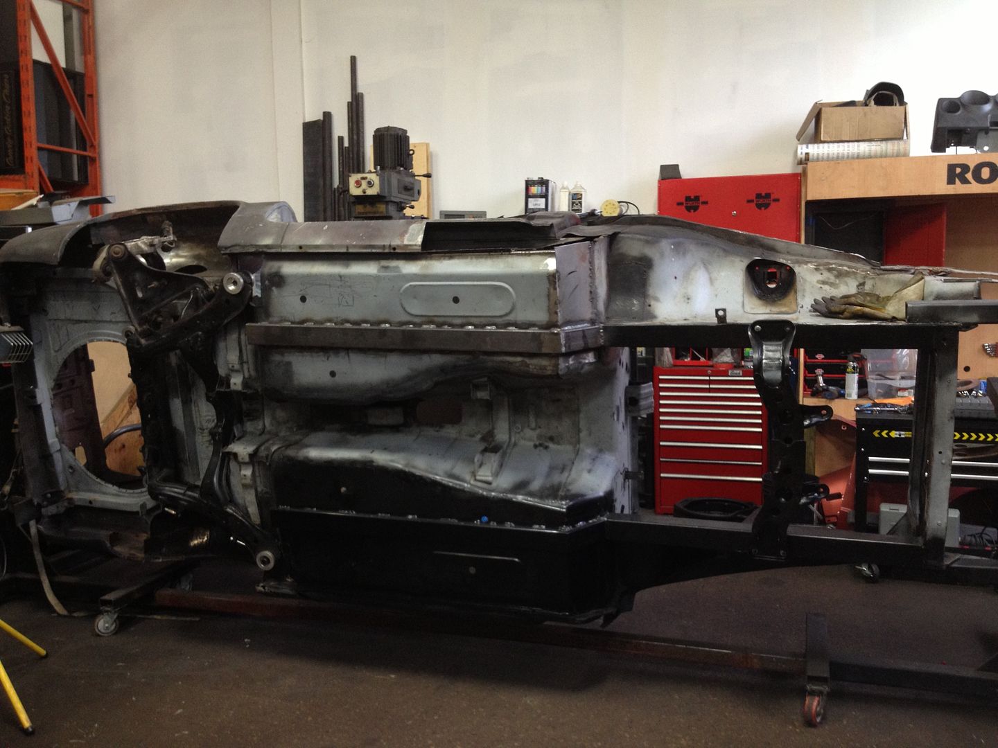
I put the Z back on rotisserie today so if this week I can come to a conclusion about the subframe height I can continue on with the cage.

great build man, very inspirational. keep up the great work

So much sex in this build

Haha thanks BK & Ahmed.

I am currently switching my rear subframe setup. The setup shown before was a 2.5" square tube mounted just behind the original mount. I am now going to a 1.5"x3.0"x.120" rectangular tubing. As I said in the last post, the 2.5" square tube allows 3.5" of wheel travel (5" max with clearancing) and the rear LCA had a 5 degree angle to the rear mount and a 0 degree angle to the front mount. From what I’ve heard, the rear mount should be parallel to the ball joint.

I also figure it is easier to shim the subframe down from a 1.5" connector if I have to dial anything in rather than be SOL.

Keep in mind this isn’t finished, it is just as far as I got today. I haven’t seen anyone do the rear rails this way but it made sense - complete clearance of the subframe, and can be triangulated. I’ll sketch it up in Solidworks this week so it makes more sense.

http://i243.photobucket.com/albums/ff286/Aaj2k5/ccdd79a3-ea78-4393-bc90-e22fc4096788.jpg

http://i243.photobucket.com/albums/ff286/Aaj2k5/DAB60969-F5E4-415C-965D-00F39EA16B43-1747-0000029B1392DD97_zps546254a4.jpg

http://i243.photobucket.com/albums/ff286/Aaj2k5/E713DA32-BE65-4F16-8D10-2C3FBF1726A2-1747-0000029AD2AD828B_zps07cc57cc.jpg

http://i243.photobucket.com/albums/ff286/Aaj2k5/9C178755-3F89-4F0C-8A20-195255800F63-1747-0000029AE1BD7BDF_zpsca976092.jpg

http://i243.photobucket.com/albums/ff286/Aaj2k5/A2A3C295-AF5F-4769-BD08-64FF9F41D522-1747-0000029A08A8D363_zpsa07eb89e.jpg

Removed the old 2.5"x2.5" Crossmember.

http://i243.photobucket.com/albums/ff286/Aaj2k5/97C68FA5-AAE4-43CC-BBD3-8C8A63B68937-8247-00000A9661A20AEC_zpsd375d7fa.jpg
http://i243.photobucket.com/albums/ff286/Aaj2k5/50D64711-2FA7-4E44-A808-3B05D4001419-8247-00000A954B22C5E5_zps0510a118.jpg

New 1.5"x3"x.120 cross member - just roughed for now since I didn’t get the M20 Socket head shoulder bolts in time.

http://i243.photobucket.com/albums/ff286/Aaj2k5/88447653-B23B-47EB-9142-008E6ADF096E-8247-00000A9557291096_zps0a9aed20.jpg

Clearance to bulkhead. I added 3/4" angle to the bulkhead for strength in that corner, notched the bulkhead and the angle for the 1x3 horizontal piece. Brought a tube from the frame rail down to this at what worked out to exactly 45 degrees :smiley: 
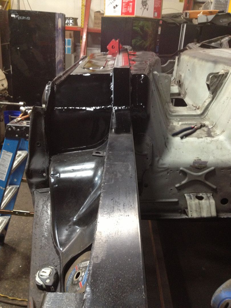
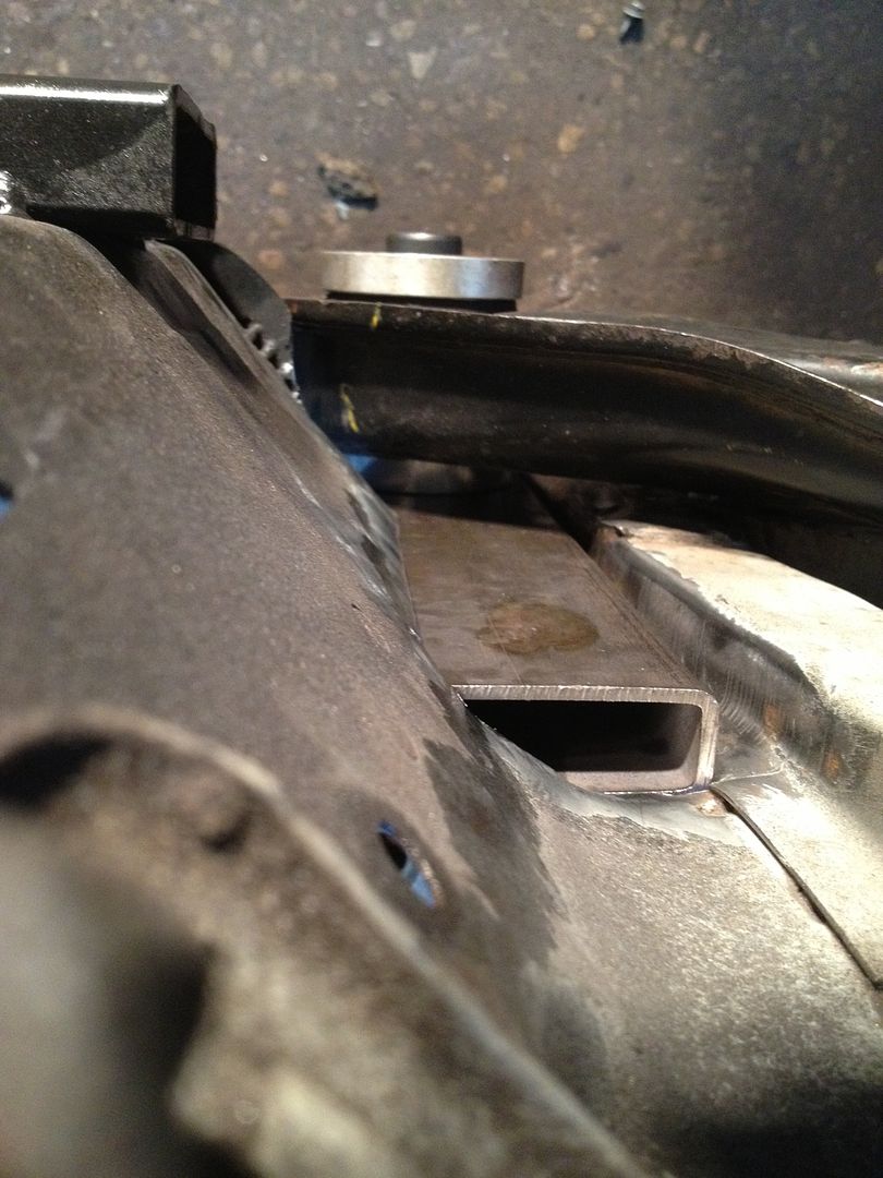
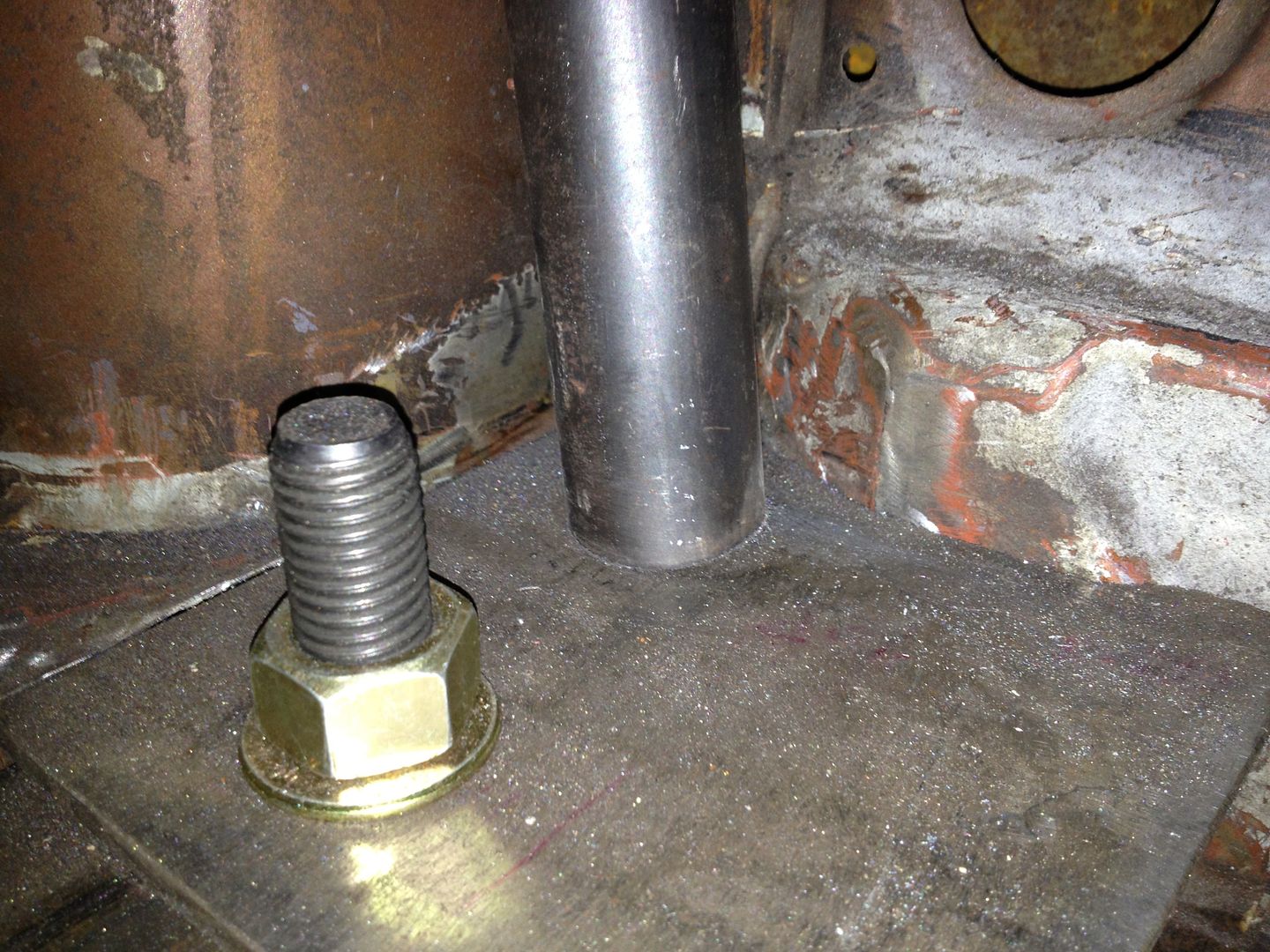
Also added 2" angle 6" long to brace the factory crossmember where this 1x3 meets it.

http://i243.photobucket.com/albums/ff286/Aaj2k5/8C1751BA-D062-4E1A-A02F-B1D3D1D46D94-8247-00000A959F5190F5_zpse1ca761e.jpg

http://i243.photobucket.com/albums/ff286/Aaj2k5/349A4A03-2E26-4F68-A385-65D7CA8FF333-8247-00000A957999CB5E_zpsf727e4d6.jpg

http://i243.photobucket.com/albums/ff286/Aaj2k5/AB073D97-726E-4432-BC25-1D5E052EA3FE-8247-00000A956795D0C0_zpsbfb4d8ad.jpg

http://i243.photobucket.com/albums/ff286/Aaj2k5/B7019B9C-F0DD-4E24-B291-E3559B2E6874-8247-00000A956DB2130B_zpsa7e49373.jpg

http://i243.photobucket.com/albums/ff286/Aaj2k5/DF7A421B-9891-4D73-A283-A25F157E0BFC-8247-00000A95336ABA73_zps7be39c1e.jpg

http://i243.photobucket.com/albums/ff286/Aaj2k5/8448FB6A-4CF0-40A0-AD9A-6C01CDA338DD-8247-00000A972880BBF1_zpsd5372dc8.jpg

http://i243.photobucket.com/albums/ff286/Aaj2k5/E1B1A39E-5D39-4AE8-95EF-D160EF7FE518-8247-00000A973BBBD805_zps8b356409.jpg

Also picked up one of these for dirt cheap since the powdercoat was dinged on the front face as shown. 50% off for a pure aesthetic? Sold!

04-07 Cadillac CTS-V Brembo Front Caliper

Pistons: 4 x 40/44mm

Total piston area: 8.61 sq. in. 5554 sq. mm
Rotor Thickness: 1.26 in. (32 mm)
Part #: (L) 89047727

http://i243.photobucket.com/albums/ff286/Aaj2k5/EAD7D94A-A485-4AC4-9EA4-44FF85C8D4FF-8247-00000A96961ECC95_zps7d74ef44.jpg
http://i243.photobucket.com/albums/ff286/Aaj2k5/010fd2a7-3398-48cc-a601-aac91140b21d.jpg

I’ve been called in to work every weekend so this has not progressed all month :frowning:

Matched the DS fenderwell to the PS

Turned these up on the lathe since I don’t like paying $$$ for $3 in 6061 T6. Solid diff bushings - new to make a few more for the front of my Q45 diff.

Started sketching my front knuckle to design CTS-V Brembo caliper adapter.

Old setup:

New setup - not shown but welded pipe nipples into the holes like the old setup to sleeve bolts/help crush.

Opened up the subframe bushings to 20.25mm

Tacked in place after measuring from a number of reference points.

I’ll have new front subframe mounts done next weekend and continue on with cage A-pillars!

Respect man, one of these days when you finally get her done I’ll want a ride :slight_smile:

      • Updated - - -

Oh and I’ve decided I want to sell my 240sx, not sure if you’d be interested as it’s parts galore (custom koni 8611 race shocks, all spl arms, 6pot front/4 pot rear wilwood bbk, amongst other stuff).

Soo this happened a few weeks ago

So I was out of the game for a bit, but starting back into er now.

Took this setup

And stuffed it in here

Had to chop the factory transmission mounts off the car to get the TR6060 to clear but there is plenty of room in there otherwise. The shift is about 2" too far back but that is no sweat since it has a 6" long bracket connected to a rod which can both be shortened.

The steering rack is going to be an issue but ill deal with that after I make my mounts.

Also, this is waiting for a rainy day.

While I’ve been down with the ACL tear I had some powdercoating done by JP @ Strip Tech. My Cusco RUCA’s as well as the LQ9 valve covers in wrinkle red.

http://i243.photobucket.com/albums/ff286/Aaj2k5/456DE698-5BA9-4400-86AE-8CBA5C27AC86-1789-0000034882C703AC_zpsc1e0772d.jpg
http://i243.photobucket.com/albums/ff286/Aaj2k5/IMG_2155.jpg

http://i243.photobucket.com/albums/ff286/Aaj2k5/64F8DB24-9665-4FAD-B84C-2EBADB7F9A3F-1789-000003489AFC05D9_zps89db8ff7.jpg
http://i243.photobucket.com/albums/ff286/Aaj2k5/IMG_2153.jpg

And to start rebuilding the RUCA’s since it seems like the PO didn’t know they were left hand thread… QA1 XMR12 chromoly rod ends - I just need to turn up the 3/4 to M26x1.5LH adapter this week.

http://i243.photobucket.com/albums/ff286/Aaj2k5/IMG_2176.jpg

Picked up a set of JDMFlares Wide ZG fender flares - 3.75" in the rear, 3.25" in the front. I’m not a fan of doing the usual sheet metal screw so I grabbed M8 nutserts and the tool to install them.

http://i243.photobucket.com/albums/ff286/Aaj2k5/10E7131C-408D-4145-8A30-3C4378012A2A-614-00000129848A20B2_zpsea3eaa2b.jpg
http://i243.photobucket.com/albums/ff286/Aaj2k5/IMG_2170.jpg

The interior was pretty haggard from welding the rails and sitting forever. All seam sealer is gone, penetrating welds smoothed and all the remnants of sound deadening gone as well.

http://i243.photobucket.com/albums/ff286/Aaj2k5/BF787C1F-2C1B-435A-9081-6ED4DE34E051-614-00000129D19AC3BC_zps051658d4.jpg
http://i243.photobucket.com/albums/ff286/Aaj2k5/B6B41B3F-B451-4954-B2E6-5C895D116A4A-614-00000129EF1101A3_zps5131505a.jpg

Made these up for the front cage mounts

http://i243.photobucket.com/albums/ff286/Aaj2k5/C715DE97-65BF-429D-B75F-63237AA6F49E-1789-00000349531869D6_zps95488c9a.jpg
http://i243.photobucket.com/albums/ff286/Aaj2k5/IMG_2158.jpg
http://i243.photobucket.com/albums/ff286/Aaj2k5/IMG_2159.jpg
http://i243.photobucket.com/albums/ff286/Aaj2k5/IMG_2162.jpg

Now that the front mounts are done, need to clearance the cowl a bit to allow a nice tight fit of cage to A-pillar.

http://i243.photobucket.com/albums/ff286/Aaj2k5/IMG_2173.jpg

Also need to cut some tube with an ID larger than the OD of your cage, in an odd shape similar to the pic.

http://i243.photobucket.com/albums/ff286/Aaj2k5/8C2F2FED-0B7F-4F56-989D-BF5774322FA4-1789-000003495F92F950_zpsc0886144.jpg

I still have to finish up the cowl clearancing but that’s it for today!

Hey guys, been a while since I’ve been able to get to shop.

Picked up Contano S14 5 lug hubs
http://i243.photobucket.com/albums/ff286/Aaj2k5/Mobile%20Uploads/20150116_200549.jpg

Borrowed a buddies tube bender and bought a Princess Auto tube notcher. This is the biggest POS I’ve seen but it was cheap and I needed something asap. The blue bushing housing had a ton of play to the shaft and the hole saw adapter had huge runout so I made a new shaft assembly out of some spare bearings and milled a plate with a step to align them. Popped a 3/8" hex socket into the end and pinned it so it will never spin so I can adapt to any drill and the wobble of the drill will be taken up by this adapter.

http://i243.photobucket.com/albums/ff286/Aaj2k5/Mobile%20Uploads/20150116_182431.jpg

Bent up some scrap pieces of tube to get angles right without using the good DOM

http://i243.photobucket.com/albums/ff286/Aaj2k5/Mobile%20Uploads/20150131_164710.jpg

Bent up full A-pillar bars

http://i243.photobucket.com/albums/ff286/Aaj2k5/Mobile%20Uploads/20150201_190504.jpg

Halo bar notched nicely.

http://i243.photobucket.com/albums/ff286/Aaj2k5/Mobile%20Uploads/20150201_190531.jpg
http://i243.photobucket.com/albums/ff286/Aaj2k5/Mobile%20Uploads/20150201_190355.jpg
http://i243.photobucket.com/albums/ff286/Aaj2k5/Mobile%20Uploads/20150201_190322.jpg

Front view of today’s work
http://i243.photobucket.com/albums/ff286/Aaj2k5/Mobile%20Uploads/20150201_190554.jpg

Next will be dash bar and halo to main hoop. Should I go straight back or X for the roof bars?

That cage is tucking nice up in the pillars! Quality

How much weight do you think you’ll be putting onto the chassis with this extent of work?