We are working with Mike Wood (Krazy Kid) on his 2004 VW Jetta, and together we plan to take this car to the extreme. Looking forward to the 2011 season, anticipating some quick ¼ mile runs and plenty of friendly fun on the street. This project will showcase the talents here at Albany Speed Shop and the krazy skills Mike has up his sleeve too! Mike’s car is his baby and won’t let just anyone work on it… in fact we are the only people other than himself and his close friends to ever spin a wrench on it!
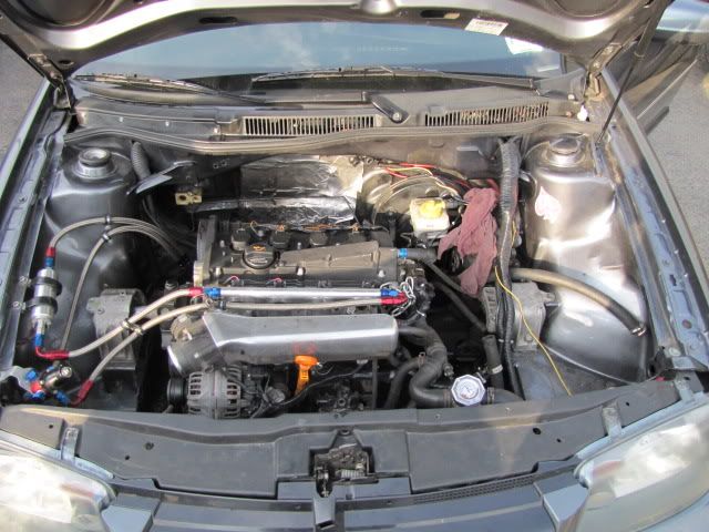
When the car first came to Albany Speed, Mike built it up rather well to start. The bottom end of the motor was built, fuel system was upgraded, a GT3076R was planted on the manifold, custom liquid to air intercooler system was fabricated. When it ran, it was a blast. With the new opportunity we have here, we hope it will be one of the most impressive VW’s in the area. Goals are 500+whp, 2600lbs curb, when Mike learns how to drive it we are looking for 11’s… all while appearing mostly stock on the outside for tearing up the streets.
Recent change in plans: [SIZE=“6”]RWD. because high power fwd gets boring… we decided to work with physics not against it. I have yet to see another rear wheel drive MK4 bodied car completed to this caliber.[/SIZE]
Link to his old build thread to see how it started can be seen here: http://shift518.com/showthread.php?t=10123
[SIZE=5]If you want to discuss the car and the build, bench race, etc… head over to: [/SIZE]http://shift518.com/showthread.php?t=20045
So enough talk, let’s start burning metal!
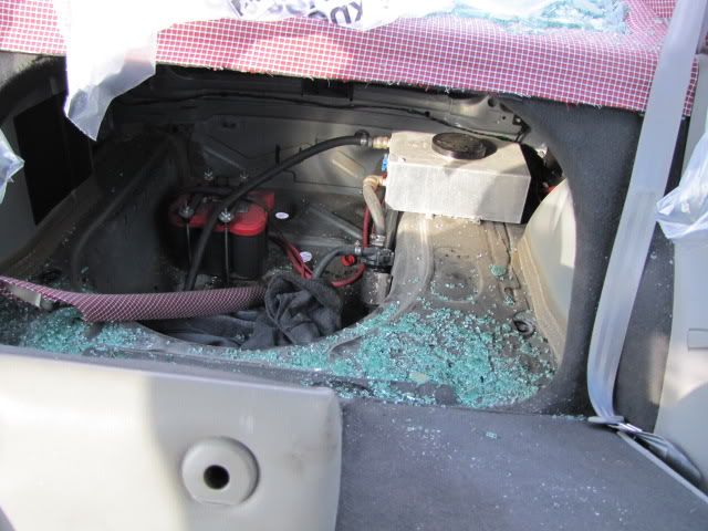
After some hooligans broke into it, this is what was left. They broke into the car, took all the Autometer digital gauges out, the turbo, intercooler, charge pipes, as well as caused plenty of body damage.
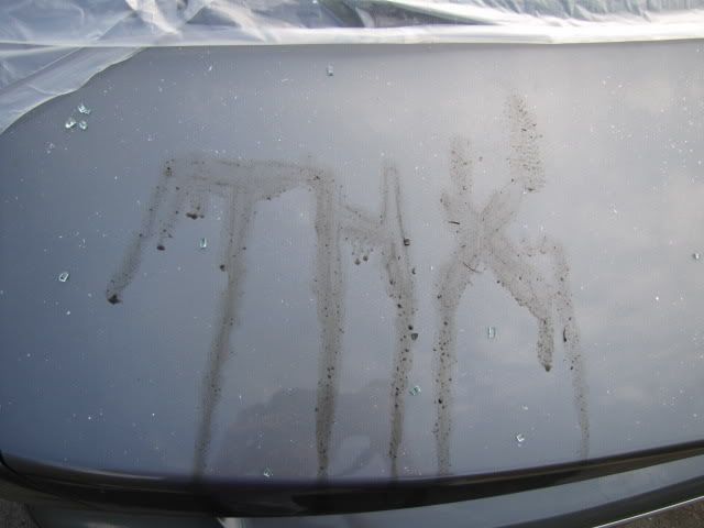
But at least they were thoughtful and said Thank You.
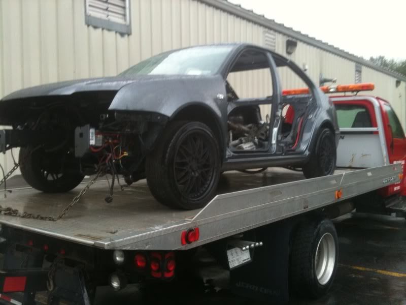
Then Mike & Albany Speed Shop sat down and came up that a battle plan then got to work. The car was stripped down and prepped for the cage.
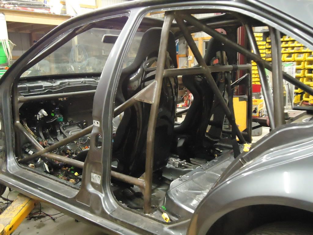
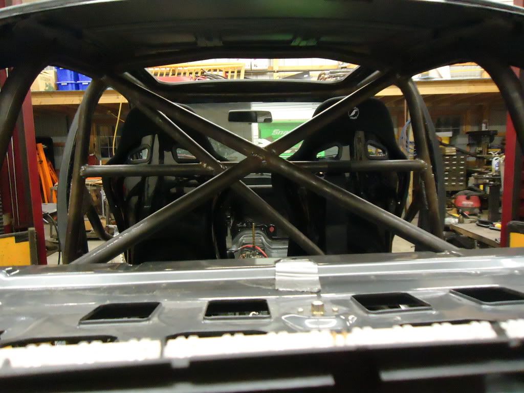
80 feet of DOM tubing later and we have an impressive cage! Mike shouldn’t have any problem sending this down the track at 140mph! Krazy Kid did all the welding, while Darryl did the math and bent the pipe.
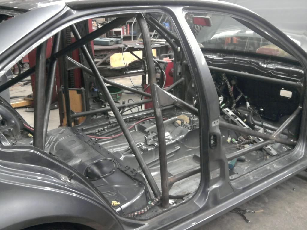
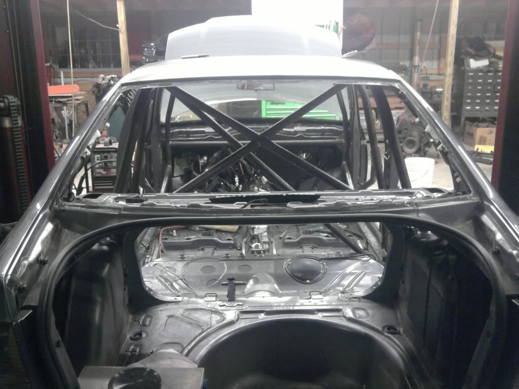
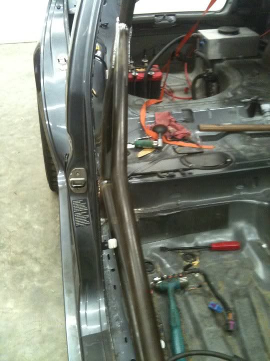
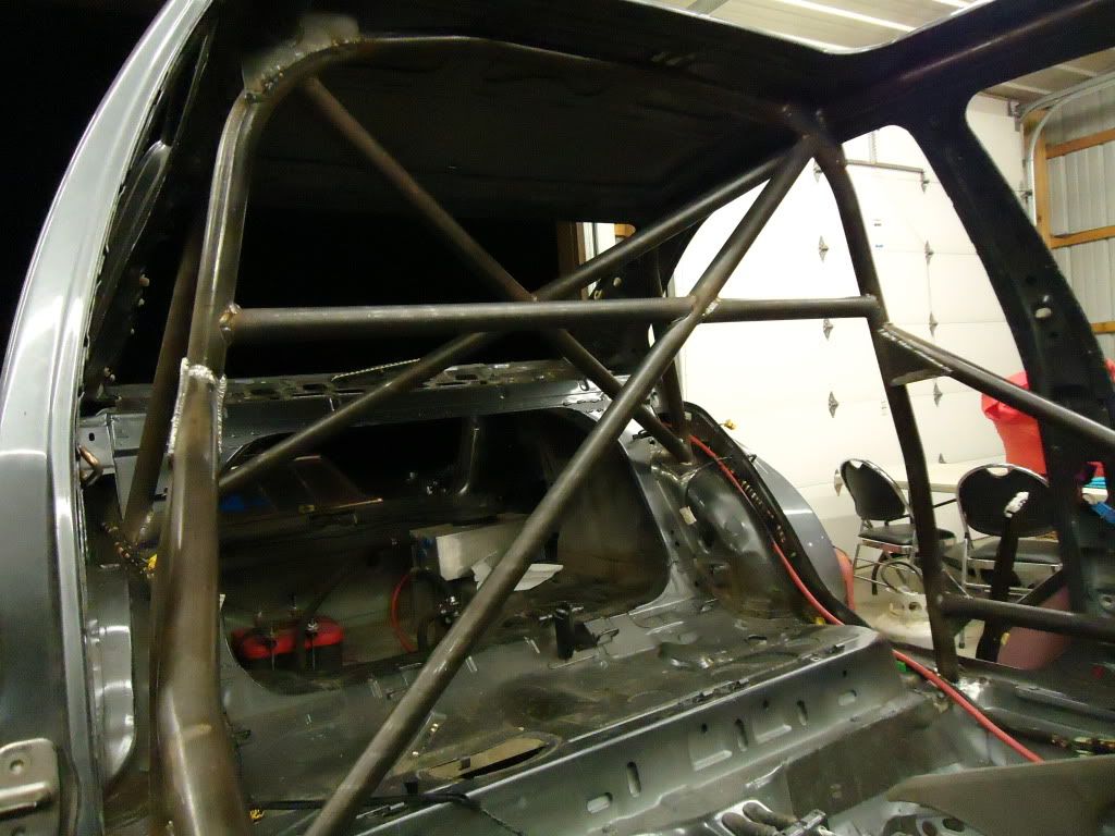
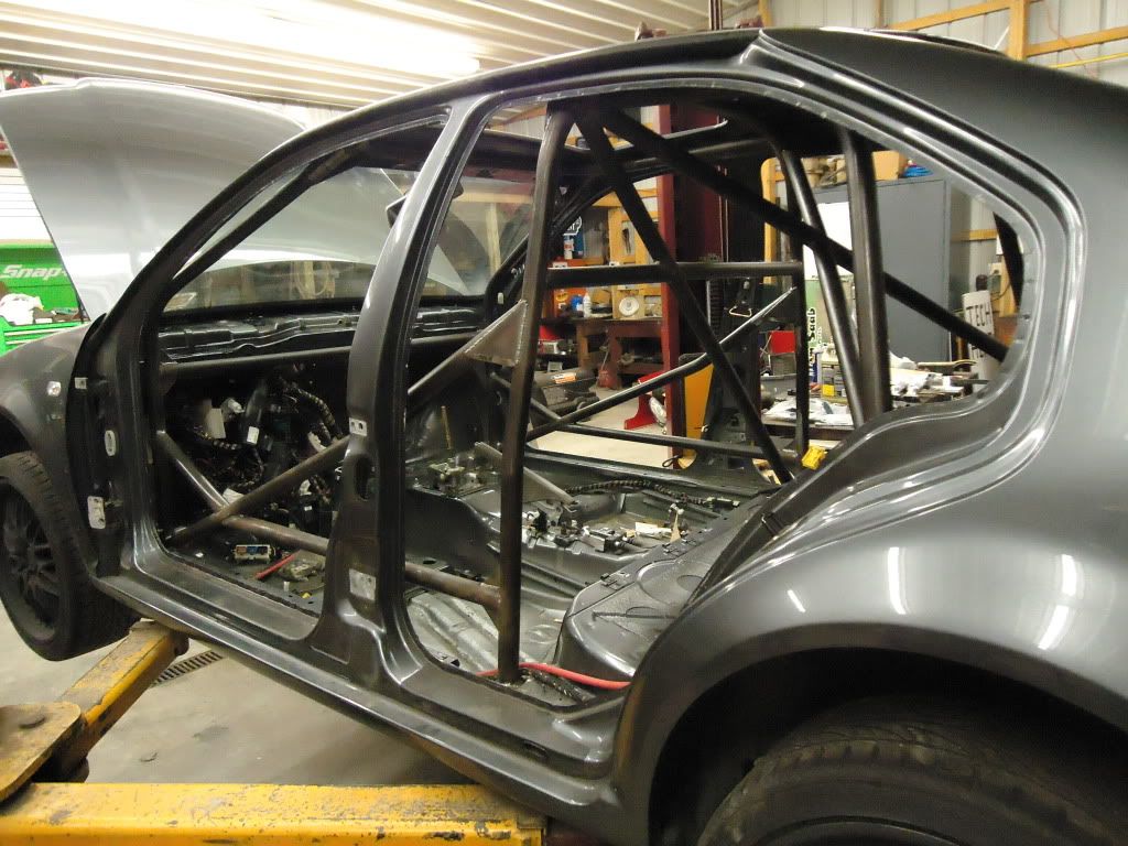
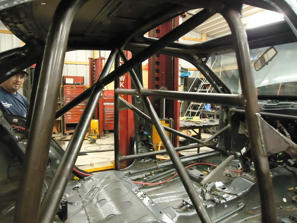
We still have a little work to do on the cage. We need to get the wiring out of the way to send some tubing through the firewall and connect to the strut tower up front. So as that progresses, we will update this section of the thread.
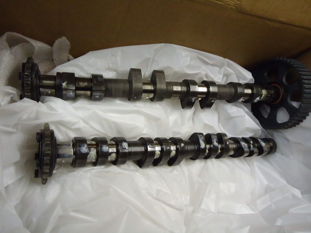
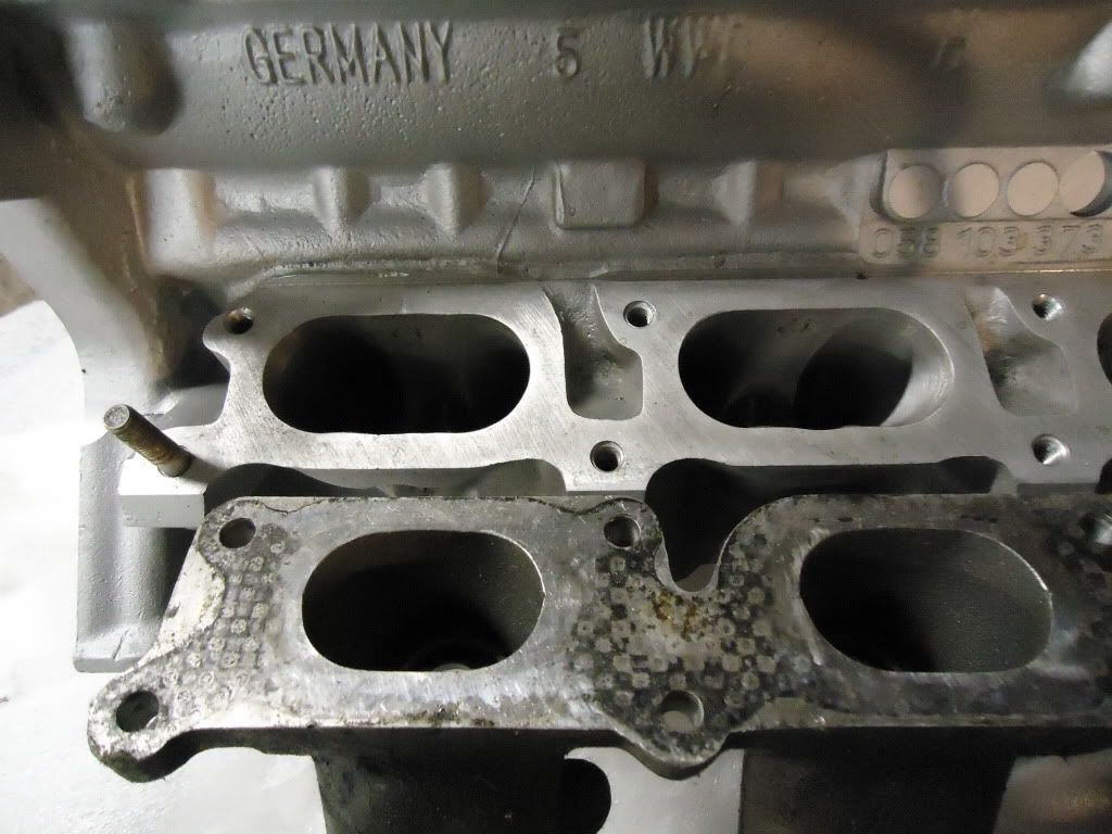
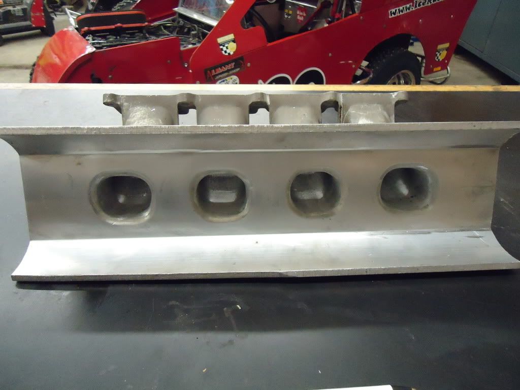
Some other goodies were delivered. Mike picked up a cylinder head packed full of the best parts available for the 1.8T. It starts life as an AEB core then it was ported out to the max! It was assembled with Schrick +1mm. valves, Schrick solid lifter conversion kit, titanium retainers, and then a set of Schrick intake and exhaust cams. This head can support revs up to 10,500RPM, and will flow %35 more than the stock head!
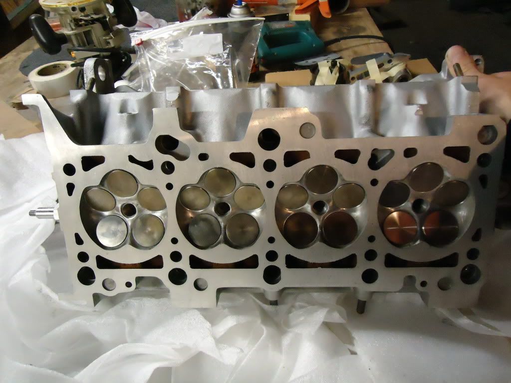
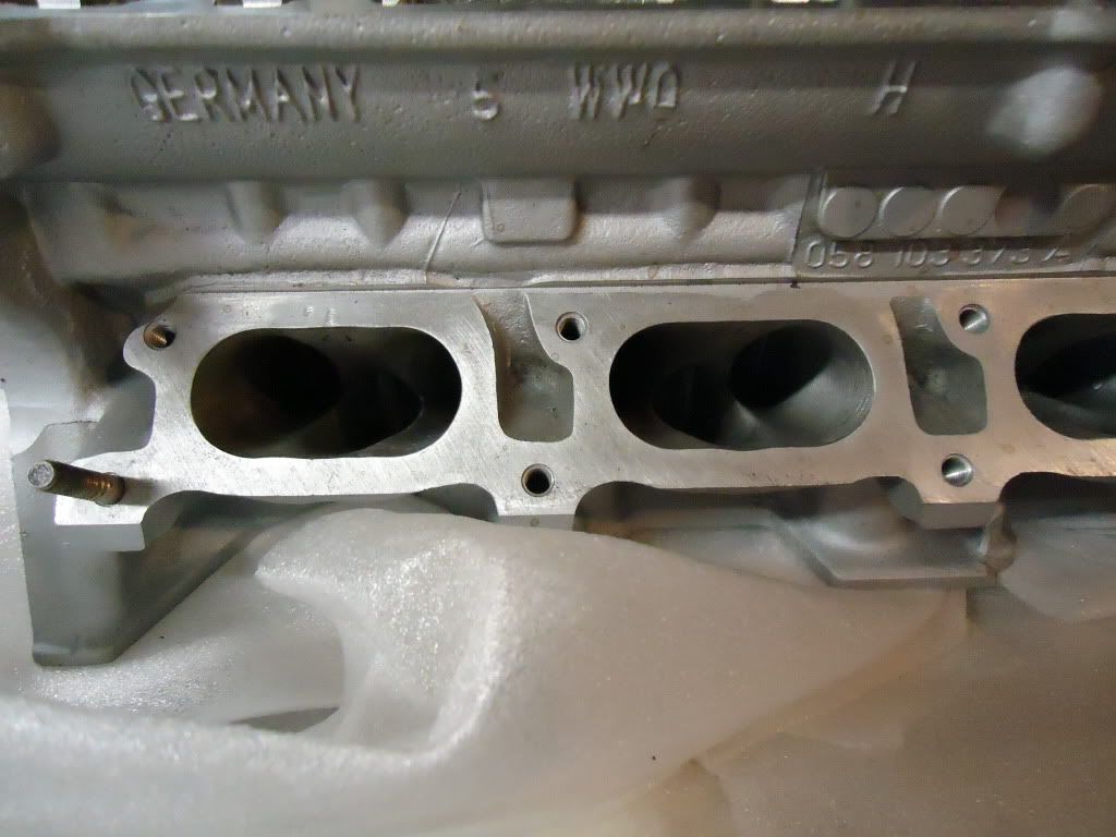
Check out the difference between the stock AWP head and the ported AEB!
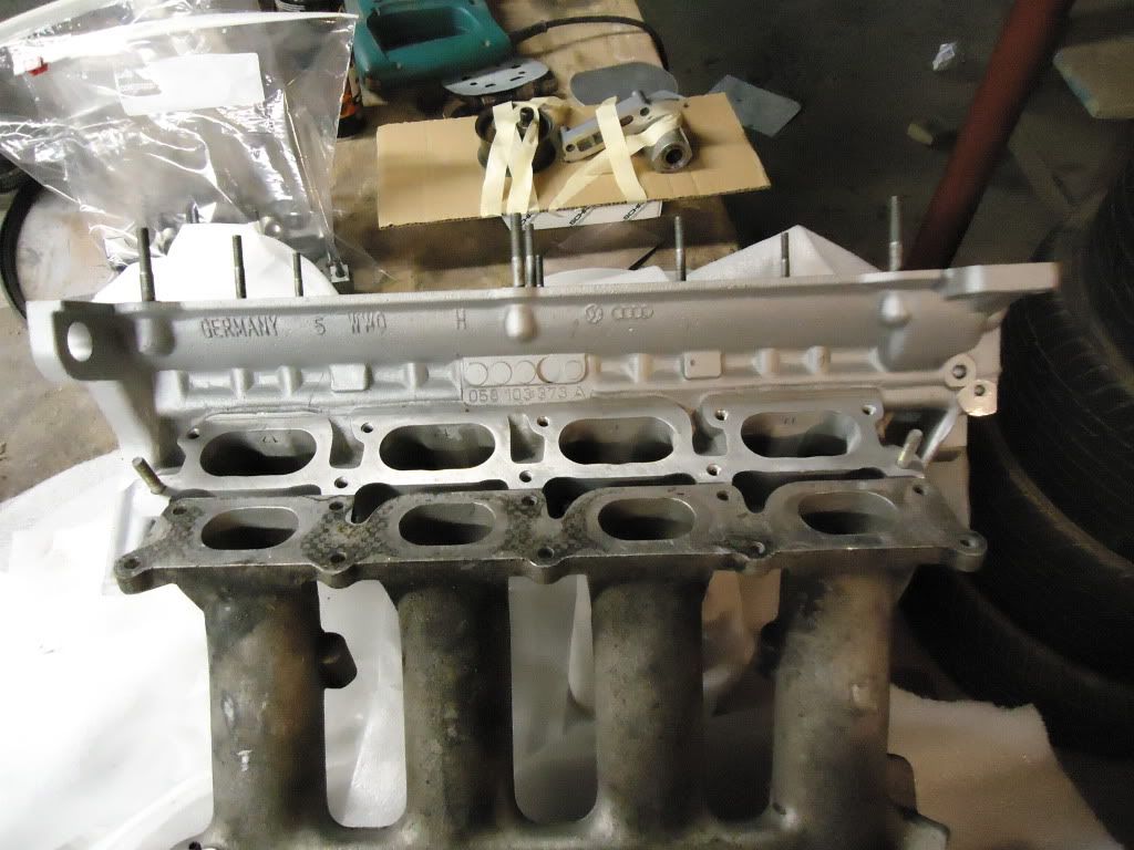
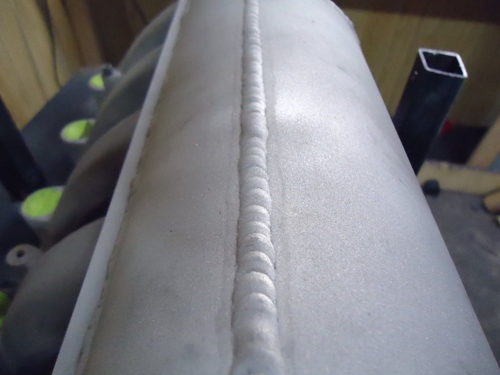
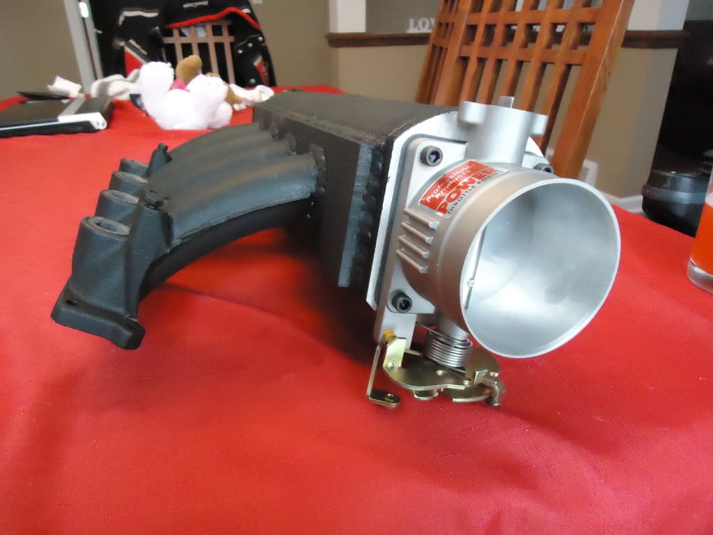
Intake manifold plans are port matched stock AEB flange and runners, mated to a custom 4.5” aluminum plenum, with a 75MM throttle body off a VW V8 motor! This should put Krazy Kids TIG welding skills to the test!
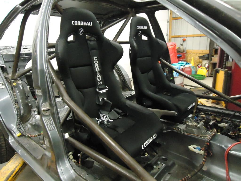
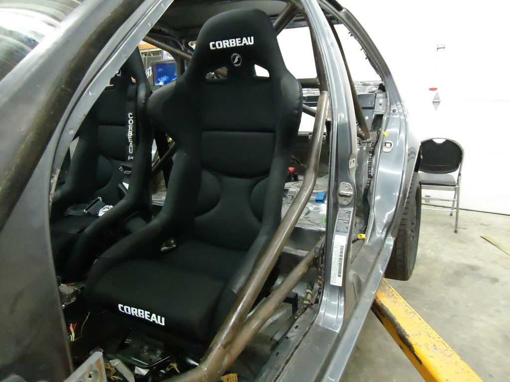
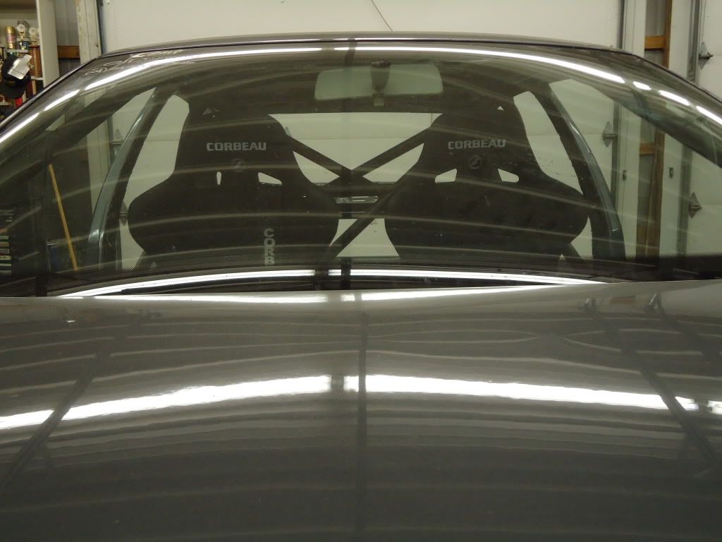
Mike and I were busy! Seats and hardware came from JVG Motorsports: http://shift518.com/forumdisplay.php?f=27. We picked up some Corbeau FX1P Pro’s, 5 point cam-lock’s and 2X locking sliders. Made some plates to mount the hip straps to the tranny tunnel and the other side mounted right up to the stock seat belt threads on the rockers perfectly. 5pt fits perfectly.
Then Mike busted into the wiring. Broke down the spaghetti mess and made some major improvements. The idea is to break up the harness into engine, brakes, body and acc so its easy to troubleshoot and omit unneeded wiring once its running. The firewall will be nice and bare when we are done!
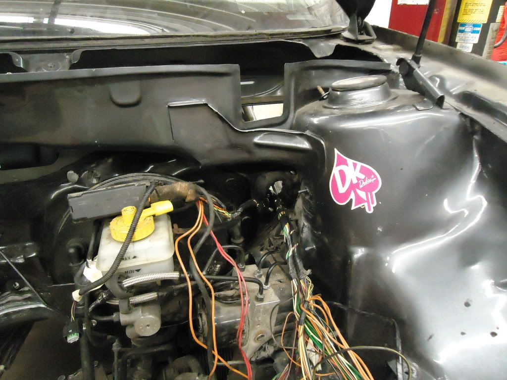
We will reloacte the ECU inside the car for easy removal for re-flashes or tapping into pin outs later on. also we have some plans special plans up our sleeves for the rain tray! you will have to wait and see!
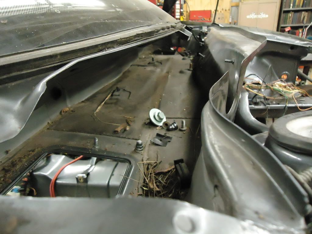
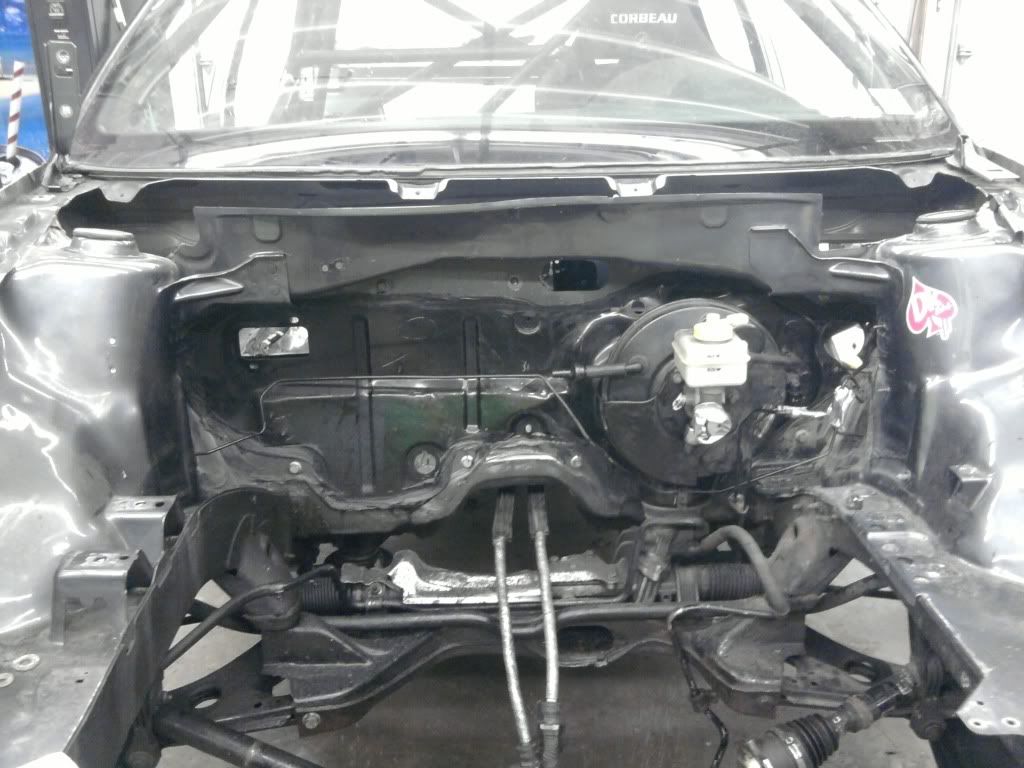
Firewall and engin bay all stripped down. ABS pump removed. We are plumbing in a proportioning valve in its place and deleting it from the ECU. That takes a big chunk of the wiring out of the picture, cleans up the enigne bay a bit and sheds about 4lbs.
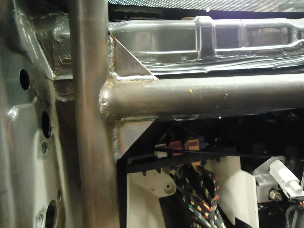
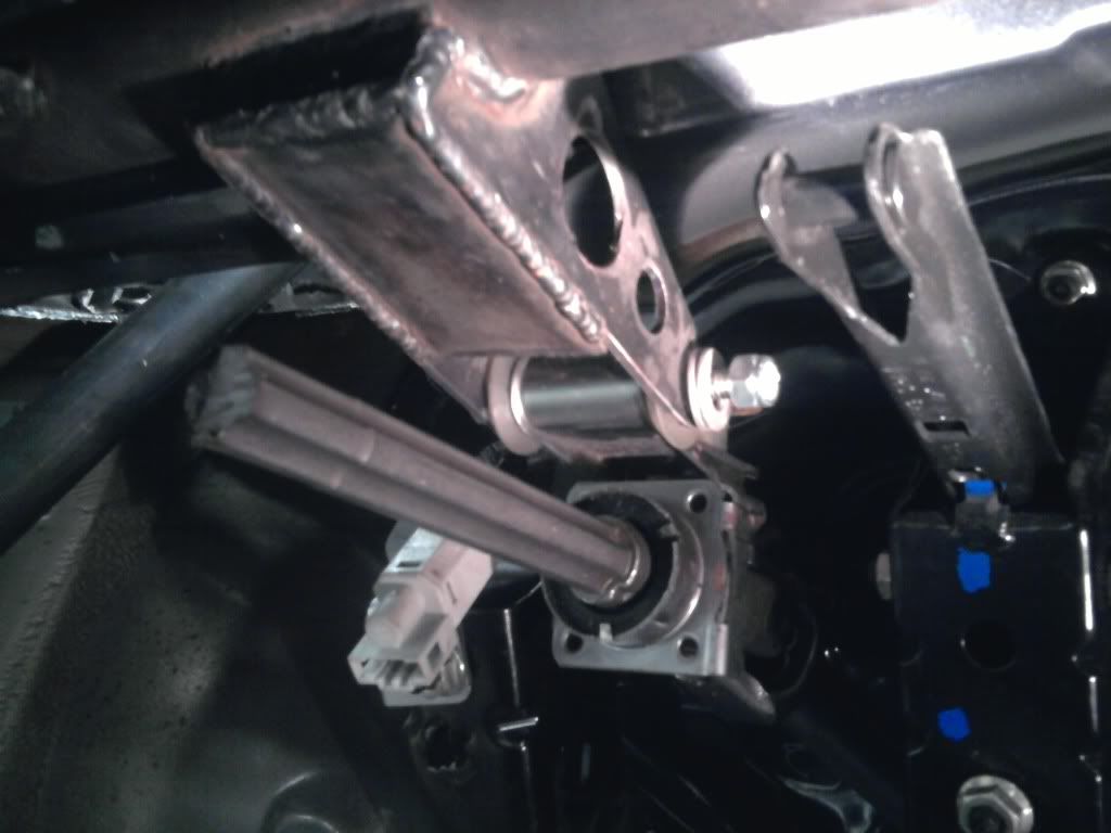
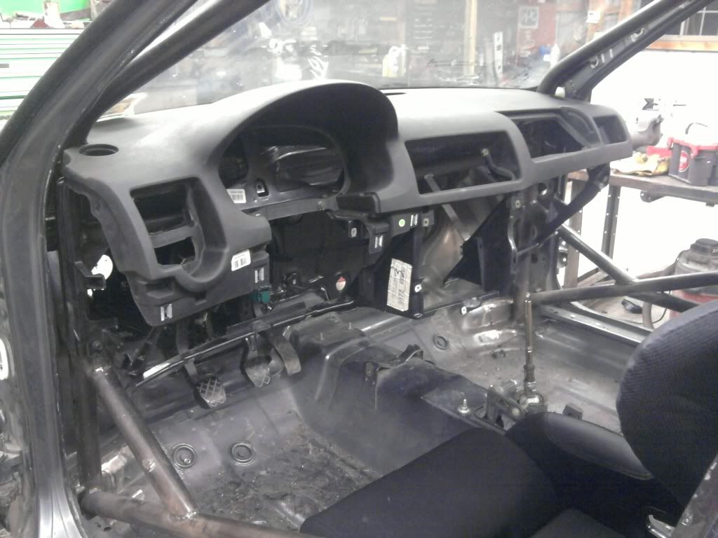
Built a bracket to support the first bearing support for the steering linkage from the dash bar. 1/8th plate, and boxed to stiffen it up.
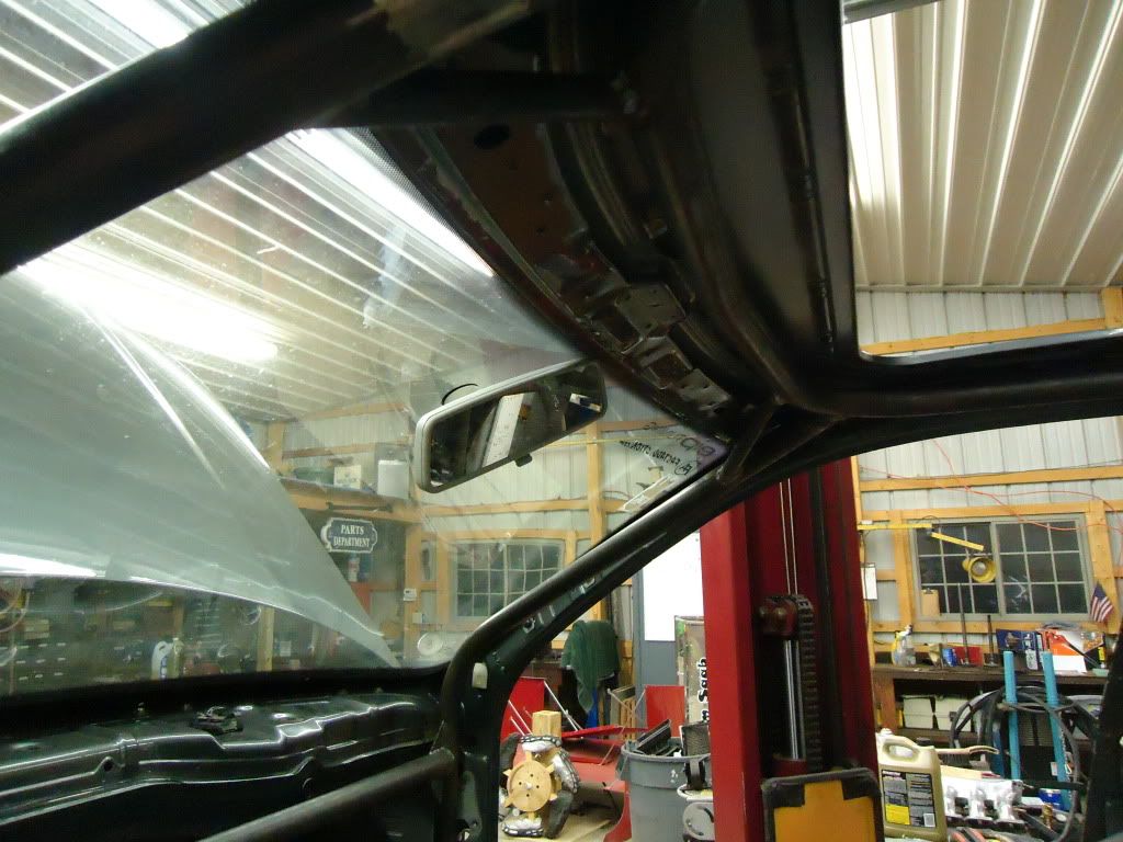
Made all the tabs to hold the dash on the cage. Five 1"x1/8" flat stock bars at attach it to the cage. Used U clips and OEM bolts to mount it too, fits perfectly and isnt going anywhere. All the side vents, radio compartment & center vents will get plated off with some 16ga aluminum sheet. Gauges and aux switches will mount inside them where we see fit. The glove box will have a sheet of aluminum behind it, framed off the cage, and will fold the ECU, fuse block & breaker blocks, ODB2 port, data logging port, etc. Stock glove box door will get put back in place to hide it too.
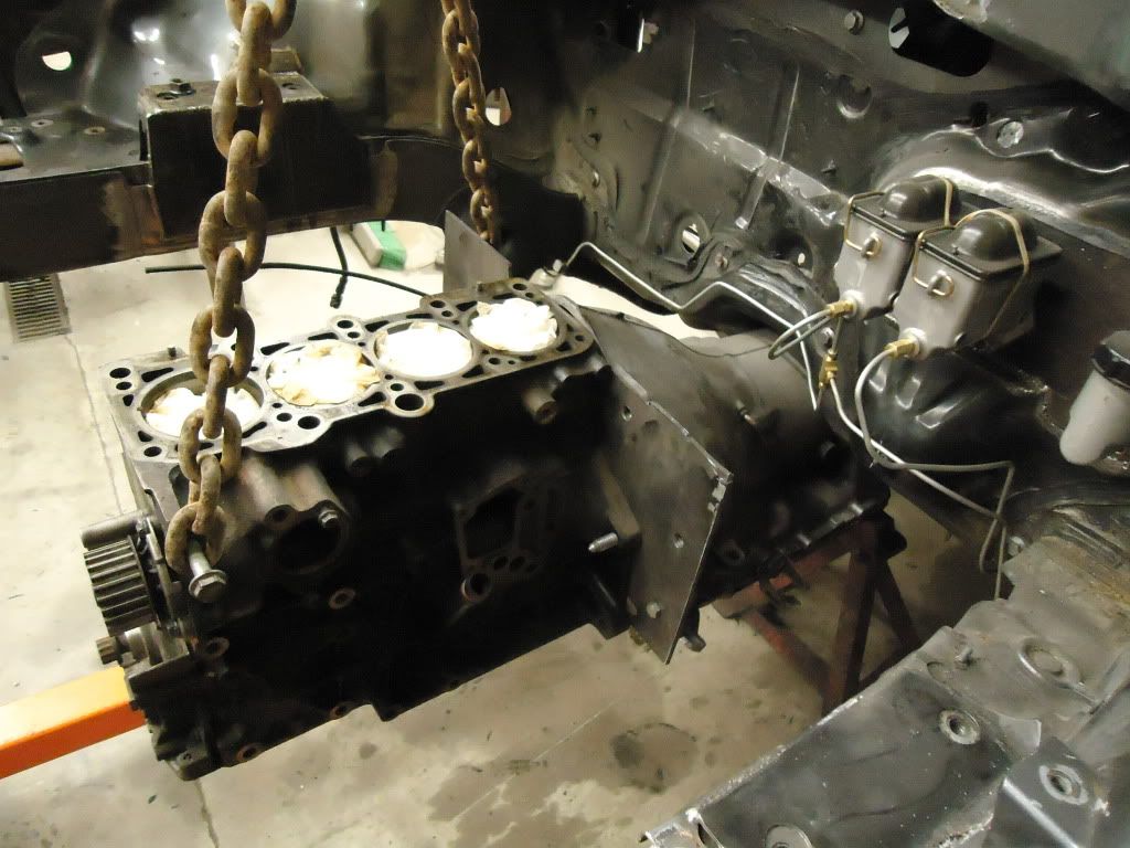
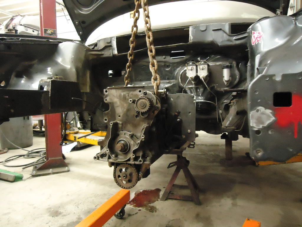
We plated the motor mounts for a little extra strength. Mike dug up an extra block and trans case so we installed them to mock the motor in place to work on building the rest of the stuff around it while we finish the new head and bottom end.
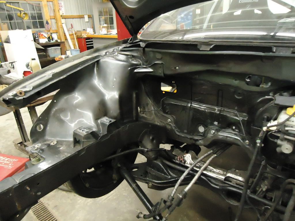
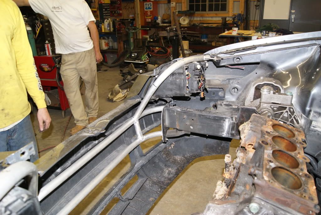
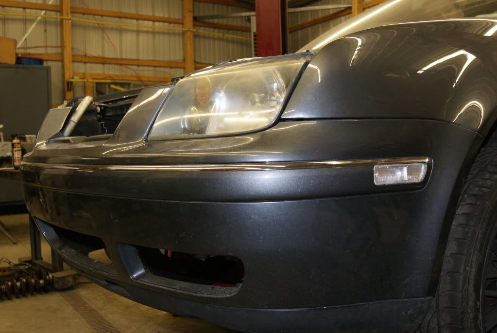
Ditched the stock radiator core support. The idea for this is to make it light, and easy to remove. just 6 bolts will take the radiator, heat exchanger for the intercooler, headlights, and what ever is attached to this off the front end to give you plenty of access to the motor & trans for repairs. It will also allow us to mount a new radiator exactly where we want it and keep it tight to the bumper cover for more engine bay room. The “foot ball helmet” was built with 1" dia aluminum tubing. We will add a DOM steel crash bar/frame horn connector to the front end just under this at some point too.
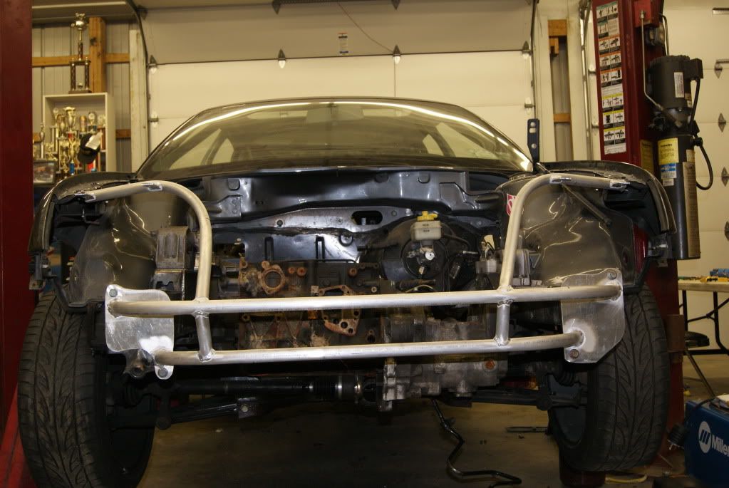
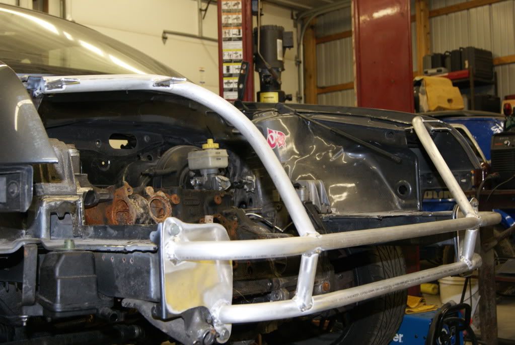
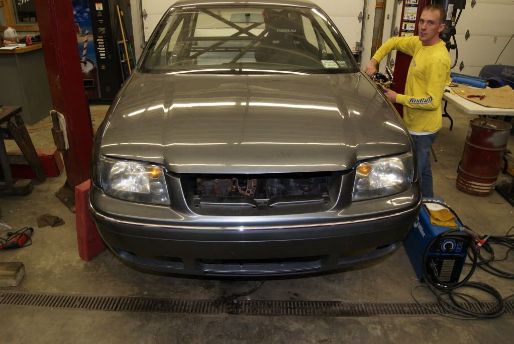
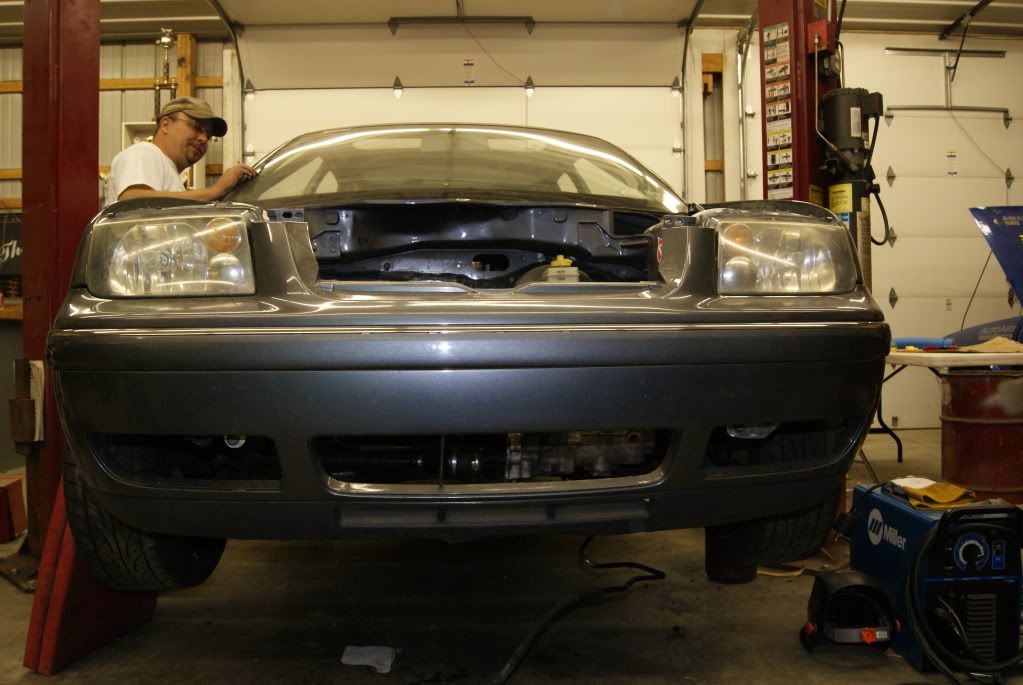
Bumper fits like a glove, headlights fit fine and the hood closes. Cant even see it or tell anything is different from the exterior.
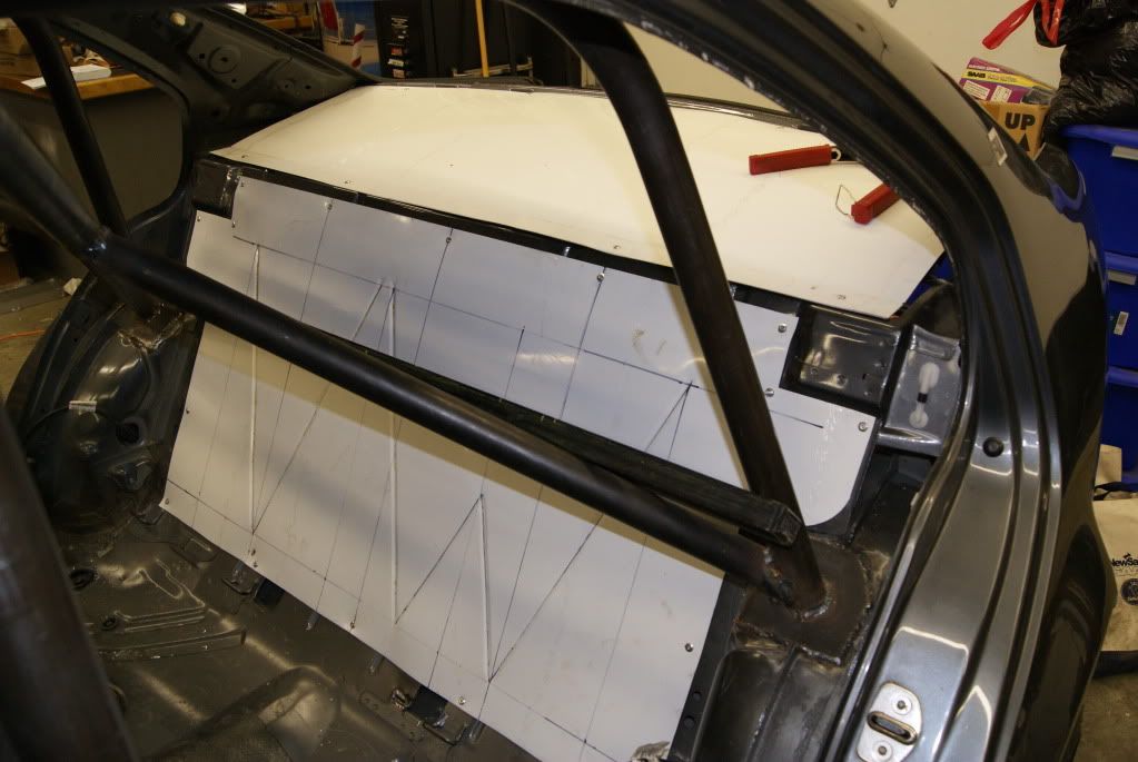
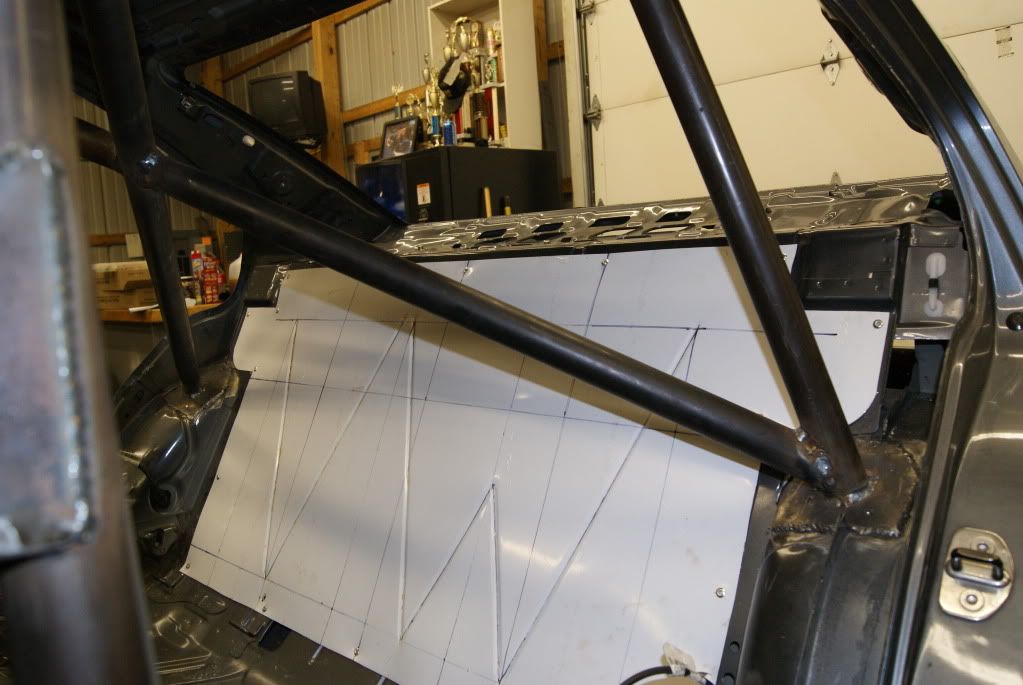
Cut, bent and bead rolled some aluminum sheet to firewall off the trunk space to keep the fuel cell out of the drivers compartment. Added a little VW touch to it.
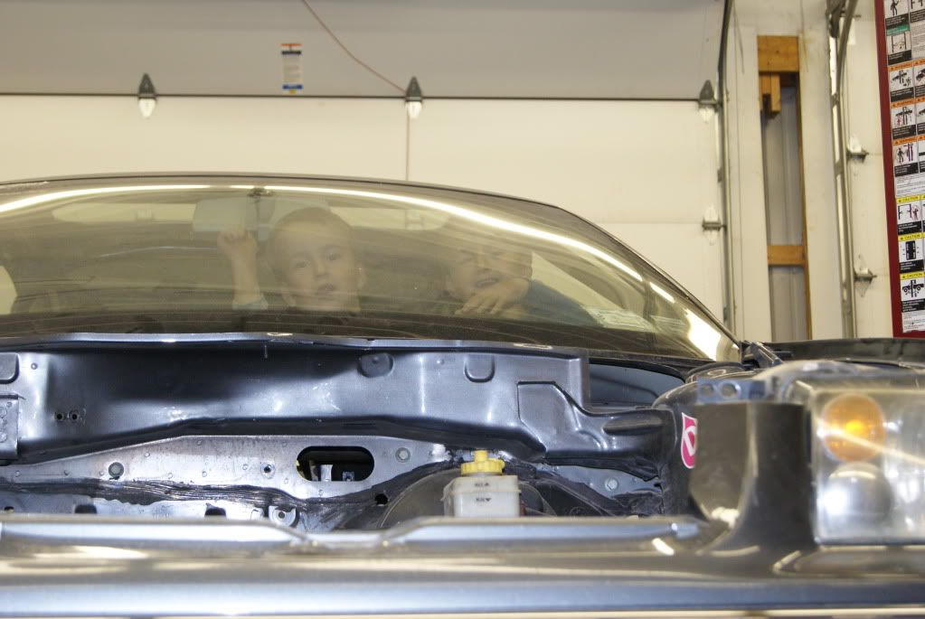
We already have 2 drivers ready to bang gears in it!!! They are Darrly’s twin 4yrd old boys, are awesome kids! They helped take the mock up motor apart; dad showed them what needed to come apart and they took it apart… impact gun, ratchets, they got the right sockets… they took the entire bottom end out of the mock up block!!! VERY impressive!
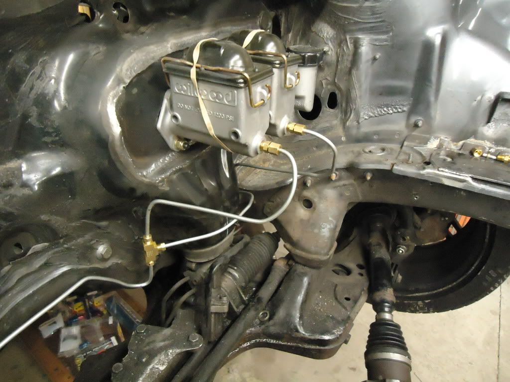
Ditched the OEM master cylinder, ABS parts, brake and clutch pedal, gas pedal. Cut out a big old section of the firewall and welded in our own section, giving us a fresh canvas for the new Wilwood dual master cylinder brake pedal setup for front to rear adjustability. Keeping with the idea, a Wilwood clutch pedal was ordered and installed with the matching cylinder for the slave cylinder. Fabricated a upper plate for the pedals and welded that to the firewall for added stiffness, locking all the pedals togehter with the firewall.
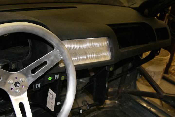
Finished up the steering setup. Made a mount for the heim joint allowing for some tilt adjustability. Installed a splined quick release, and way too big of a steering wheel! lol We have to order smaller one! Stock steering shaft, housing, controls, airbag, wheel, etc weights about 22 lbs, new system only weighs about 2lbs.
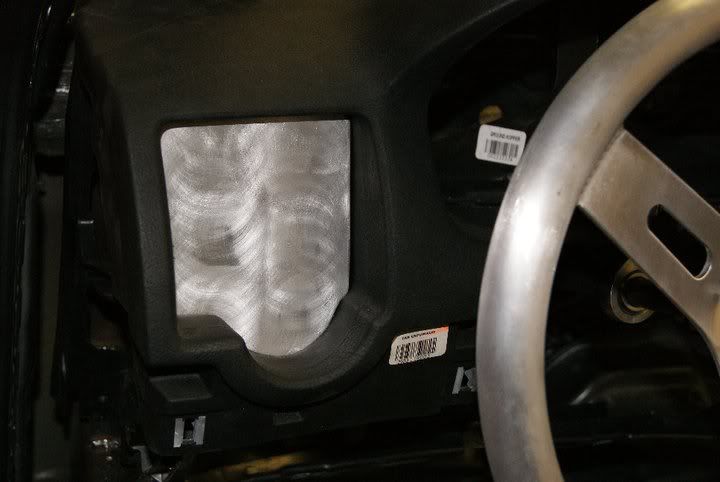
Started on the dash vent covers. Making them out of 1/8th aluminum sheet and brushed them on the drill press. light and start button on the left vent, center will get aux switches and some gauges. Radio bezel area will go back in and get aluminum sheets too. Cluster area will get sheeted and RPM and tach might end up sitting alone in there! standalone ECU for the win!
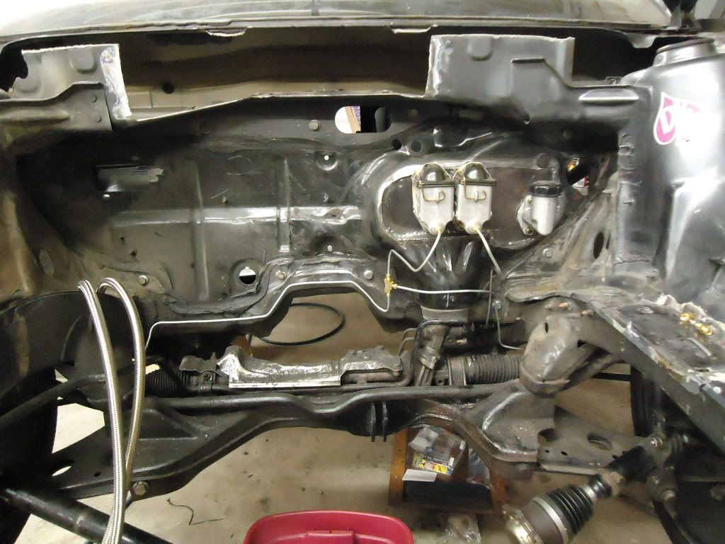
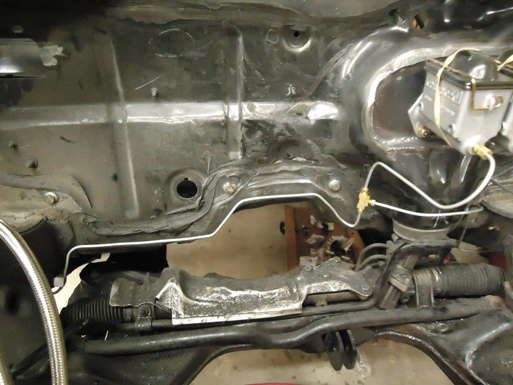
We got the Wilwood master cylinders mounted. Each cylinder feeds the front or rear brakes and the pedal has a bias adjustment built in. Plumbing was 3/16th hardline and connects to the OEM rubber line bulkhead connection at the wheel wells. I will bend up a heat shield later on to protect the line that will pass over the downepipe.
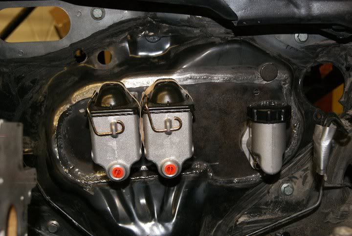
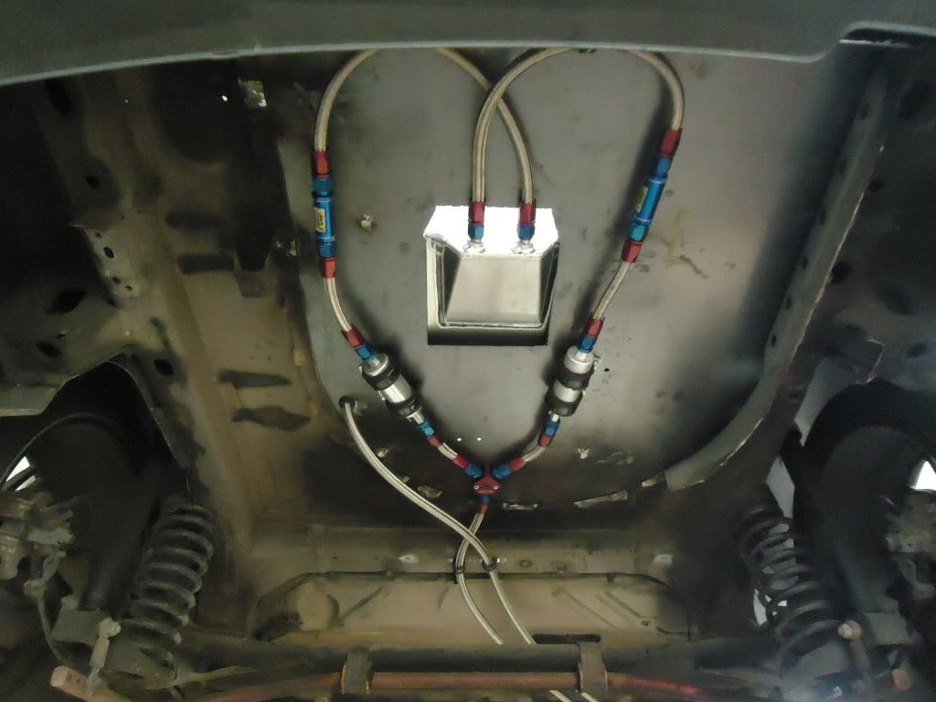
Next up is the fuel system. We cut the spare tire well out and sheeted in the tunk flush with new sheet steel. Saved a little weight and made it easier to mount stuff back there on a flat surface. All the bolts are tacked to the sheet to act like studs making it easier to remove and remount pieces if need be. Fuel cell is an RCI 8 gallon. Foamed inside and the sump exits at the rear then gravity feeds the 2 Earl 85 micron filters then the 2 Walbro 255’s. The line joins at a Russel Y block and both the feed and return line run through the frame rail up to the firewall. All the stainless braided is Aeromotive -8, and all the fittings are Aeromotive. Rest of fuel system will be put in place once the motor is back in and I can place things where they need to go.
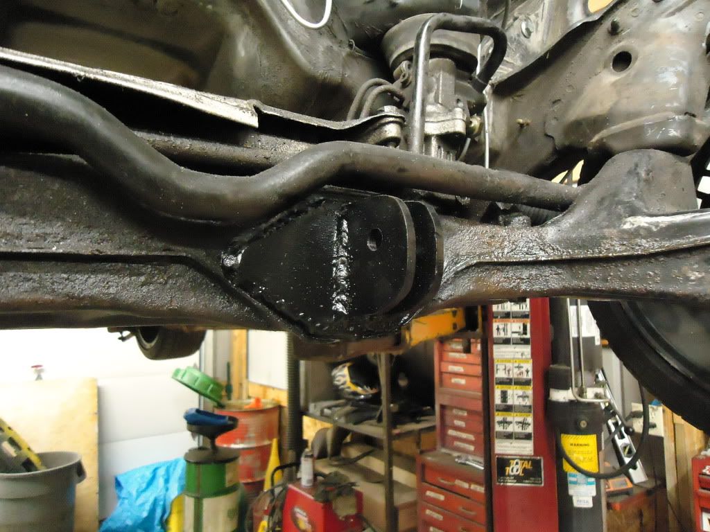
I welded a plate over the original dog bone mount on the crossmember for the solid dogbone I made with 1” dom and QA1 hiems for adjustments. Along with the solid steel mounts, that motor isn’t going to budge. The mounts are slotted too, for an inch of fore and aft adjustment for weight placement. I also plated the little bridge piece on the transmission that disperses the load to another bolt on the trans case.
I also found a copper/rubber reusable oil pan gasket finally for this motor, cleaned up the surfaces and put that on the block. Installed a new main seals while I was there. Motor should be back in soon. Cylinder head was sent to Boyds Motorworks (same guy who built my bottom end last season) to have the cams degreed in and check all the valve lash for all the solid lifters. A week or so that should be done and I can get to putting the intake manifold, exhaust manifold, finish the fueling system, radiator, oil cooler, oil plumbing, coolant plumbing… DO WORK!
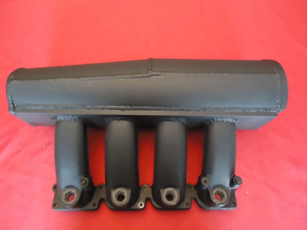
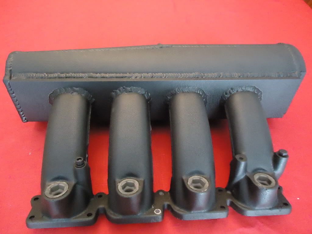
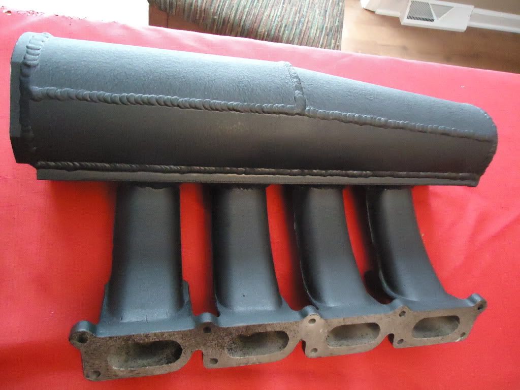
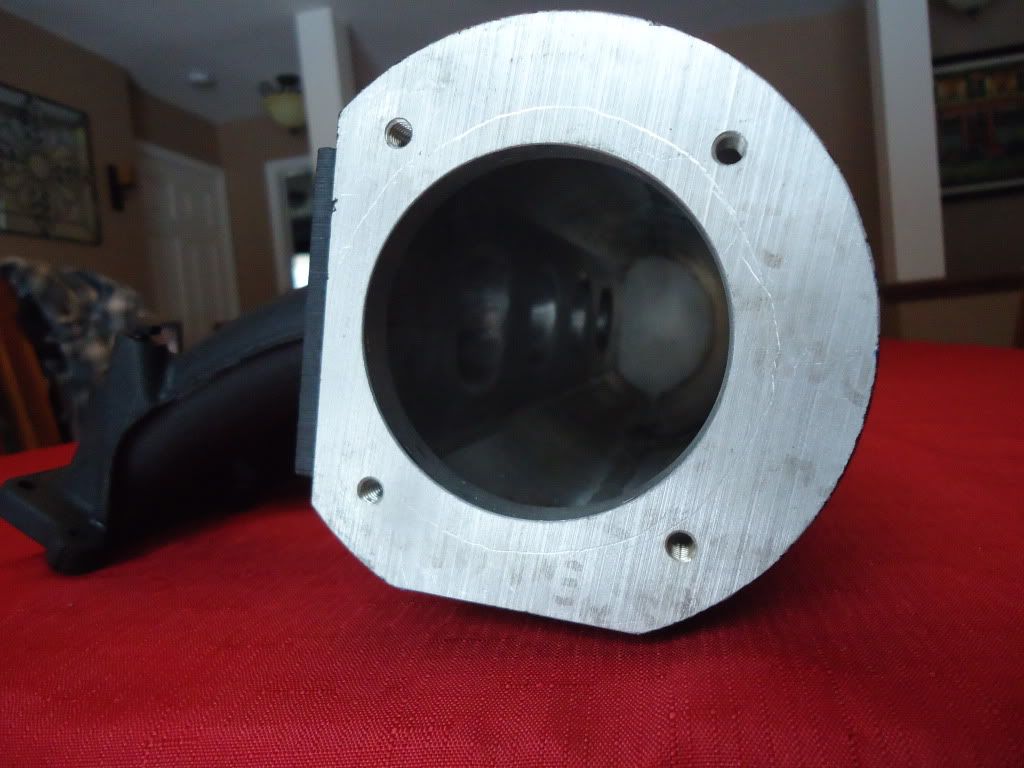
Intake manifold is done. Started life as an AEB audi intake manifold, we cut the plenum off it and left just the runners, injector seats and flange. Then welded half of an RMR D shaped plenum to a piece of 1/2" flat stock. Machined a slight recess for each runner to sit in and welded the AEB lower runners to the new plenum floor. Once that was done each runner entrance was rough machined into the plenum floor and a smooth radius was cut to make for smooth air flow.
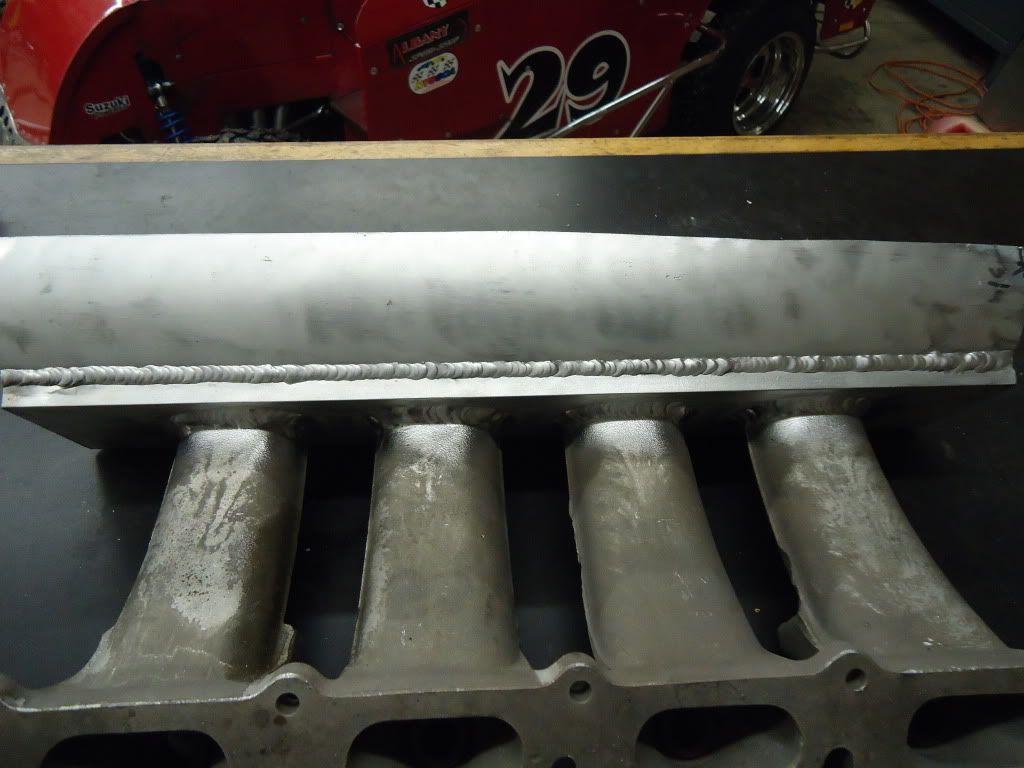
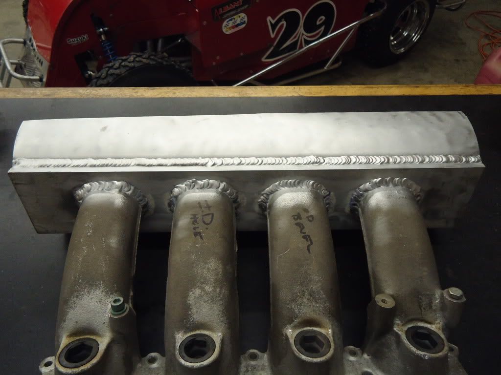
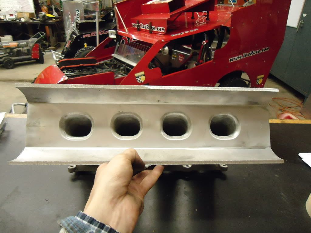
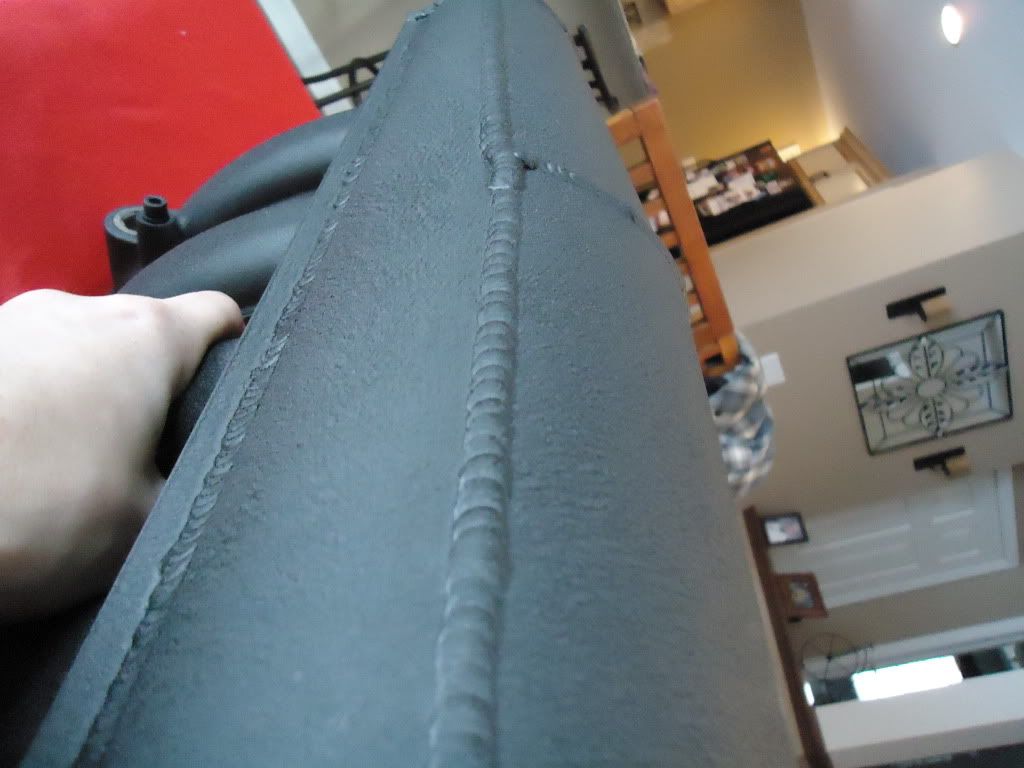
Then we designed the rest of the plenum to have a nice taper to help equal out the feed to the runners and welded the rest of the plenum up, inside too for strength. Next we machined and tapped the throttle body plate and welded it on as well as the end cap and sandblasted it for paint.
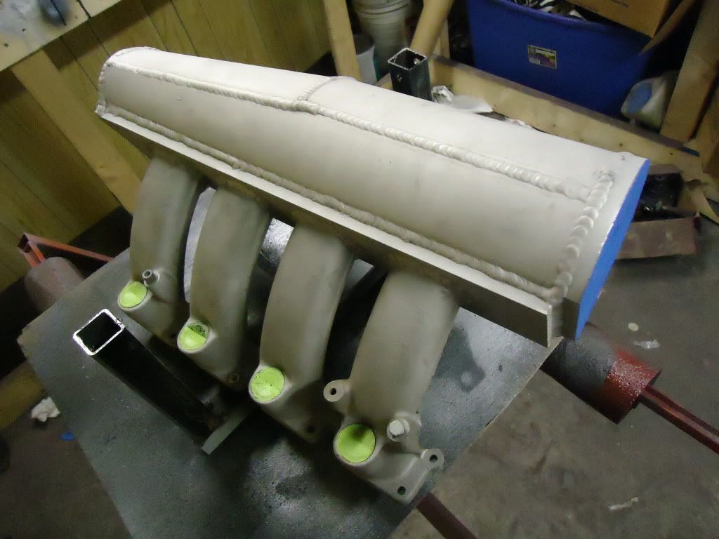
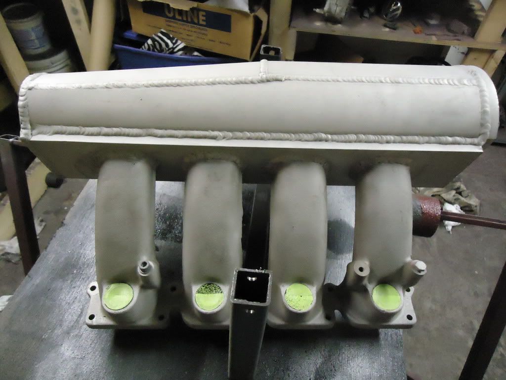

Sprayed and baked it in the over with VHT Wrinkle coat black for a simple clean finish.
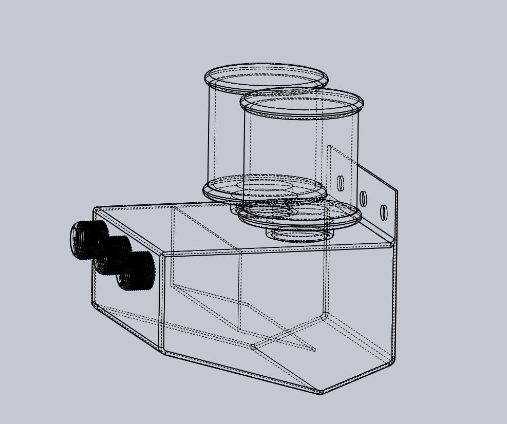
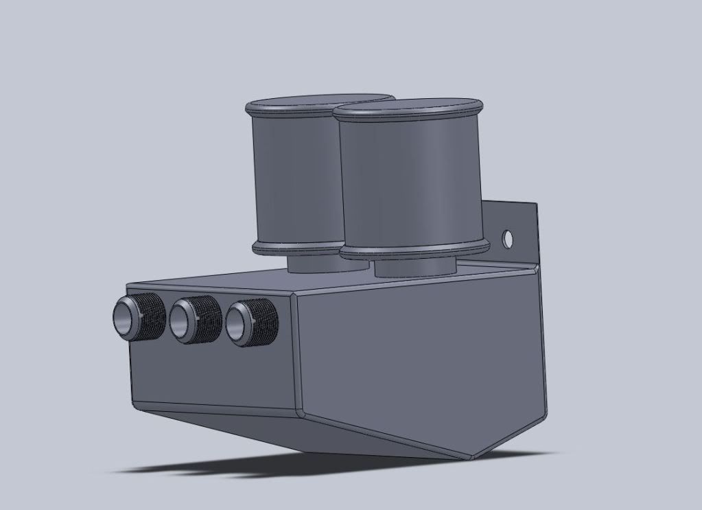
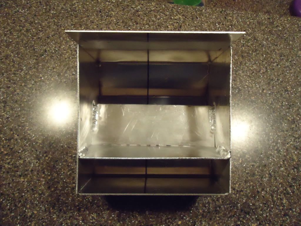
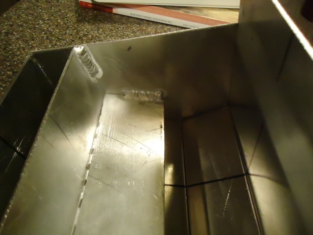
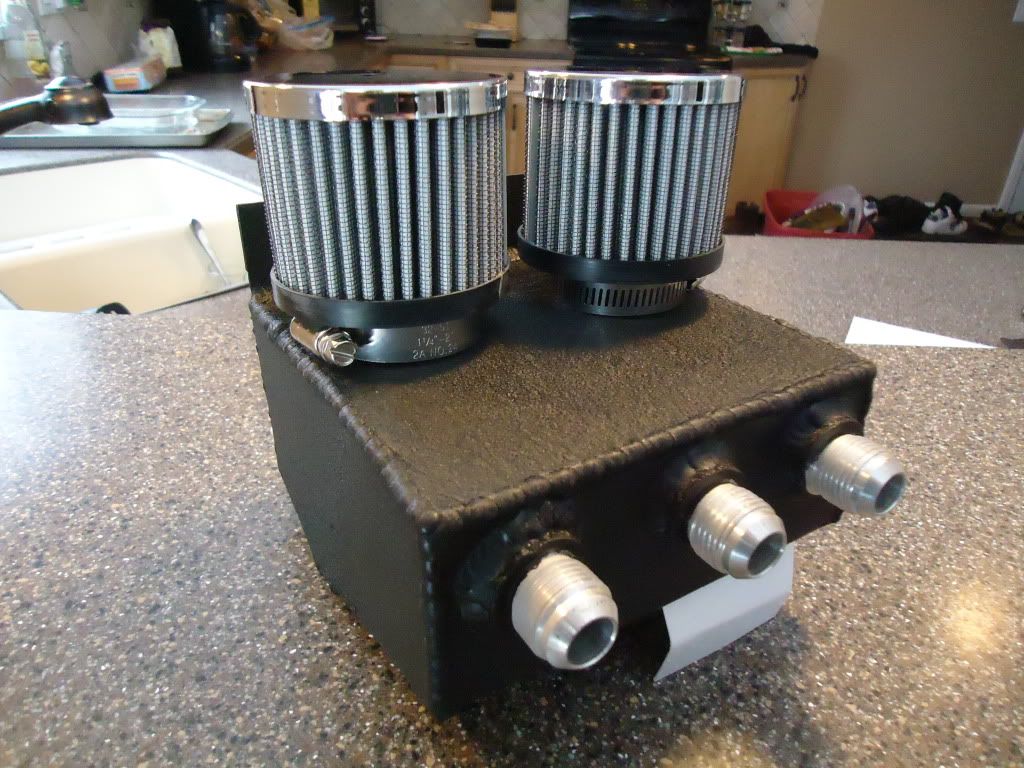
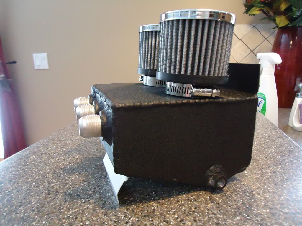
Next up was a catch can for the crank case vent and valve cover vent. We came up with a good design and went to town with a sheet of 1/8th aluminum and the sheet metal break. Internally baffled and features 3 -8 AN fittings for inlets, 2 Mr Gasket filters and a simple 1/4 NPT drain at the bottom.
RWD CONVERSION HAS BEGUN!
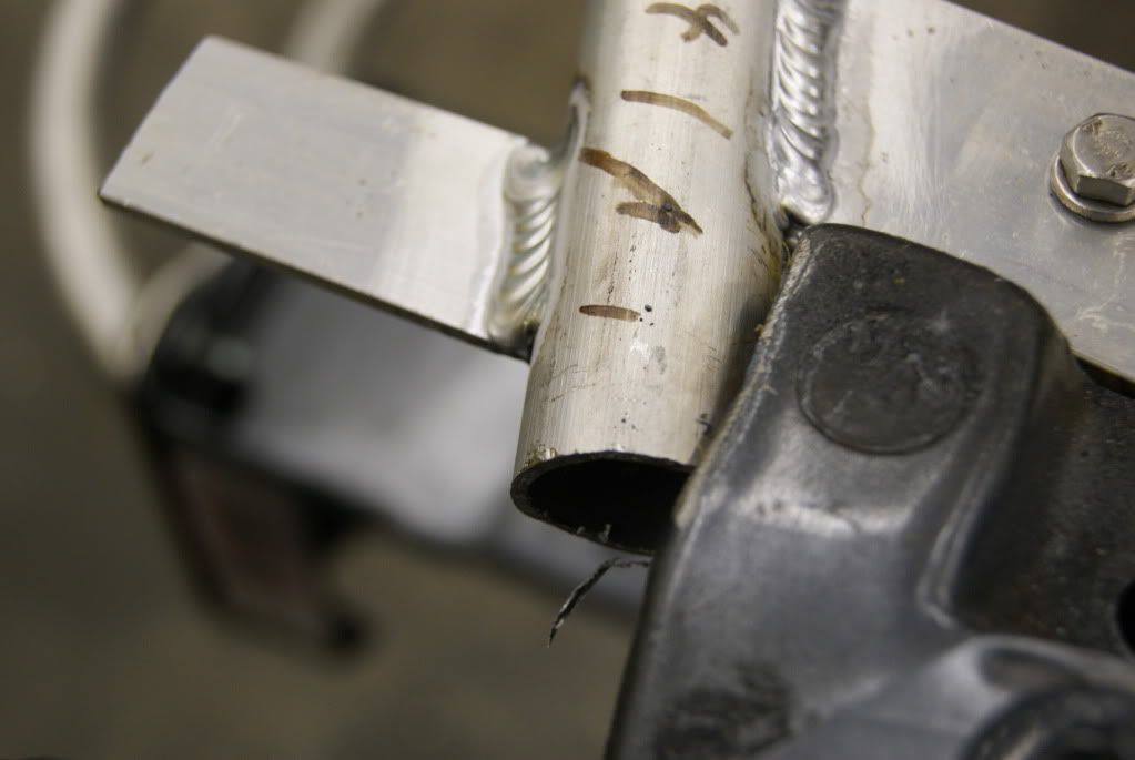
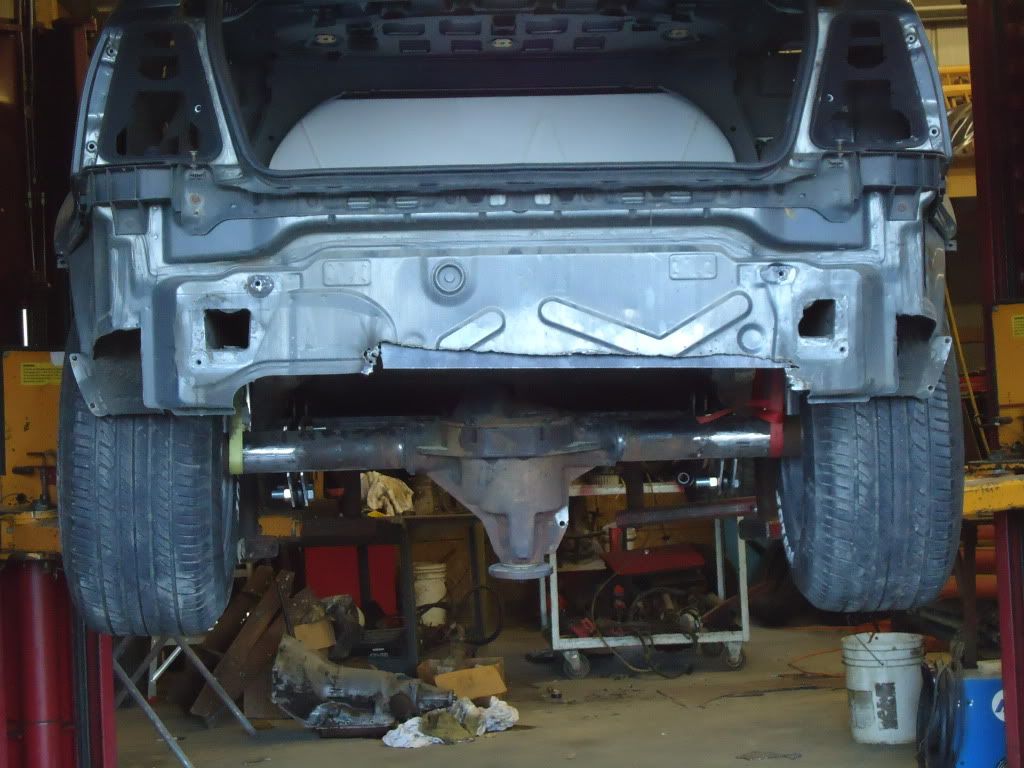
Mike picked up a ford 8.8 from a 98 explorer. For those who dont know, they are 59" hub to hub with a 3" offset pumpkin, 31 spline axles and disk brakes. We cut the long side down 3 inches, to center the differential and get the hub to hub measurements to 56", 1/4" narrower than the OEM jetta rear beam! Spun a pipe down to fit the inside dia of the axle tubes perfectly, and hammered it in at the seam, then aligned the backing plate back up and hammered the other half of the axle tube in. The sleeve inside is 8" long so it offers plenty of support to align the tubes again concentrically. Then put the axle shafts back in, and rebuilt the differential. Now when it came time to weld it, the sleeve and the axle shaft/bearings would keep it aligned. Mike tig welded it up, doing 3/4" beads alternating each side of the seam, to keep the heat from tweaking the tubes out of wack. The short side actually spins better than the OEM side! Also tigged the axle tubes to the differential housing, so they dont risk braking the 4 oem plugs and spinning the tubes. Gental kiss of a 100grit flap wheel and you cant even see the axle was narrowed!
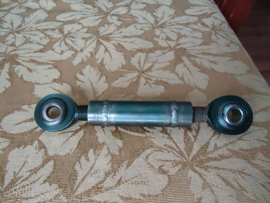
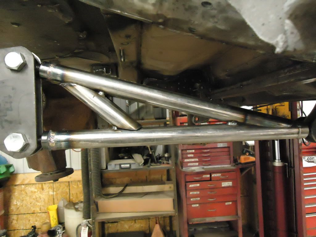
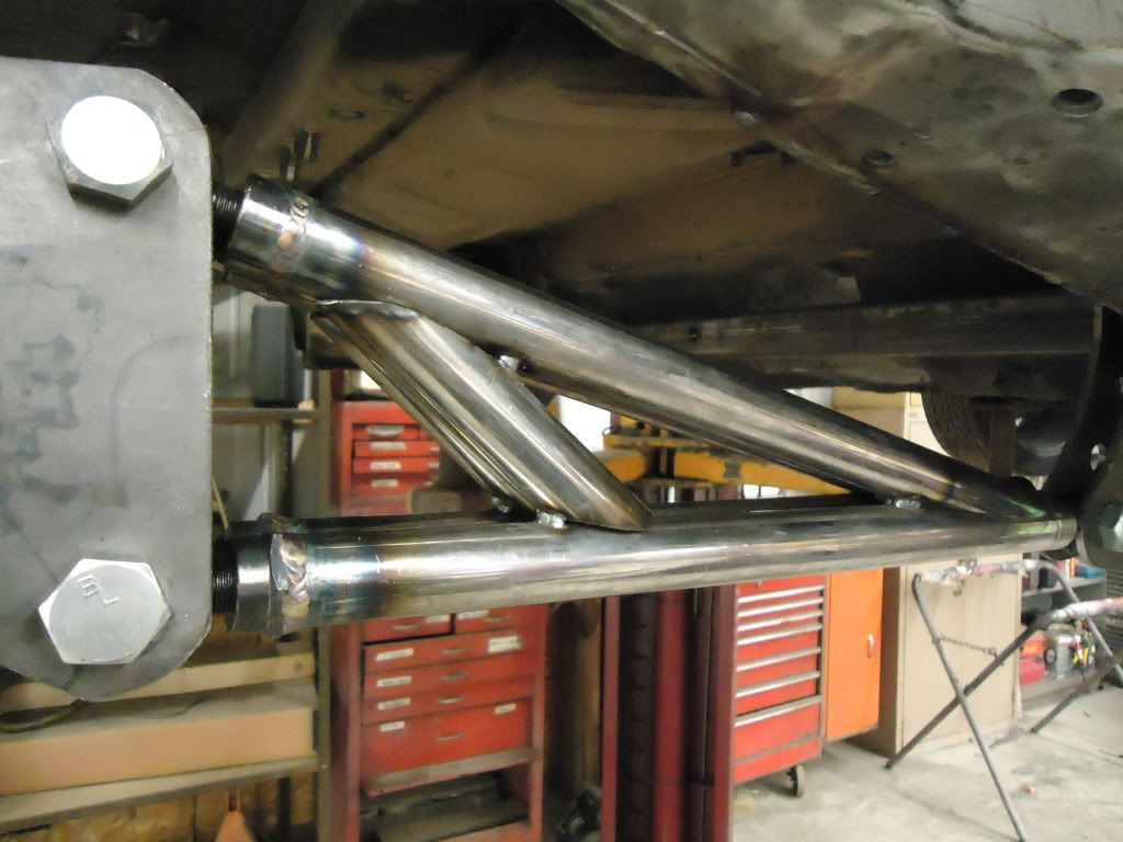
Next up was the rear suspension. While a 4 link would give us lots of antisquat adjustment the bars would be a lot longer and taller, taking up more of the non existent room under the car. We decided on a ladder bar setup, because its more compact and wouldn’t require an anti-sway bar either. Mike “modeled” :rofl the design from a well known, proven drag racing suspension company. Its amazing at what you can do with a picture, knowing a bolt hole to use as a reference size, and a digital caliper! Front bolt hole to axle center is 26" long, exactly what the “short wheelbase” ladder bar kit they sell is. The bars Mike made are 1.5" .120 wall DOM with 3/4" QA1 ProX hardened alloy steel heims. Brackets are 3/16", and once they are final welded when the car is on the alignment rack, they will be boxed in for torsional rigidity too.
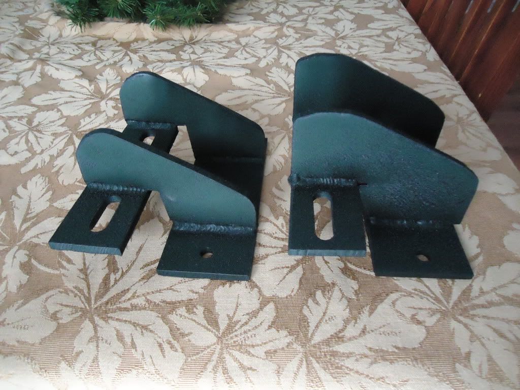
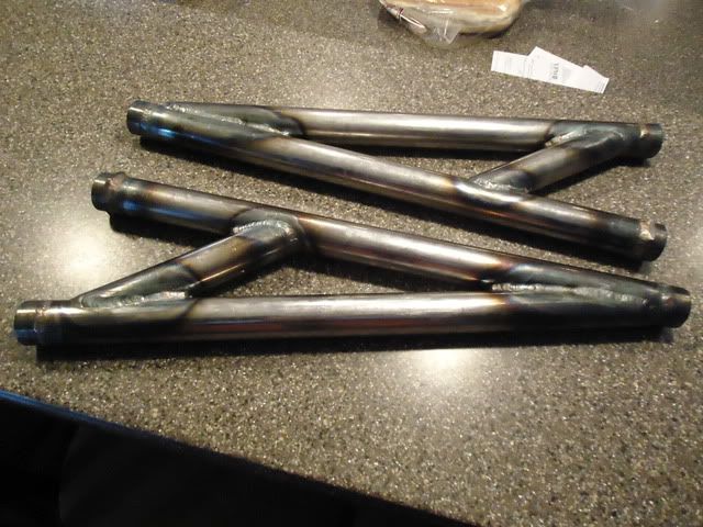
Here are the two ladder bars, side by side showing how they match up perfectly:
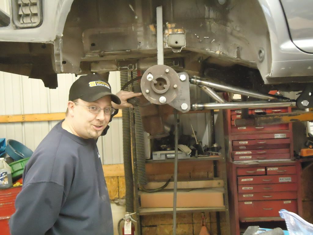
Darryl inspecting the work!
All tigged up, ready for sand blast and paint.
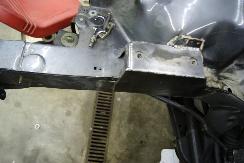
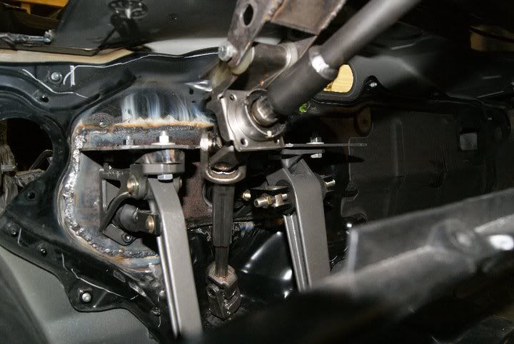
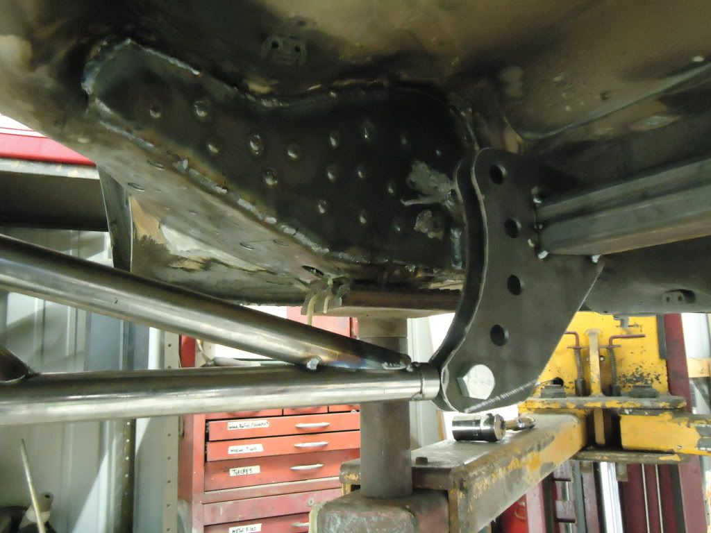
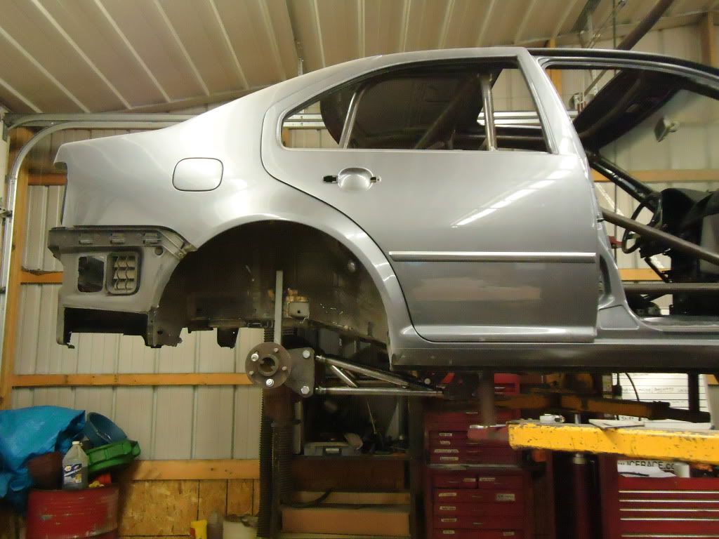
We positioned the axle under the car, with the 100" wheelbase we wanted and squared it up to the frame and the front suspension, then held it in place with some 1x1 tube welded to the frame and the axle tubes, slightly higher than ride height. Threw some safety straps around it to the strut towers in case the tack welds let go, we didn’t have an axle fall on our head!
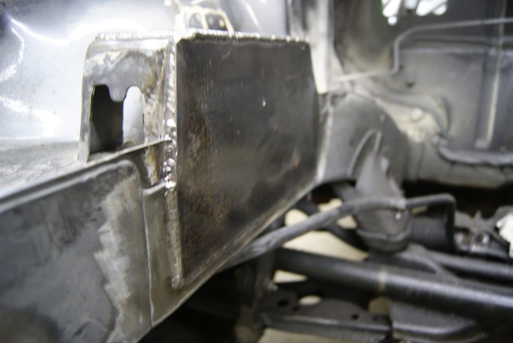
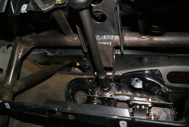
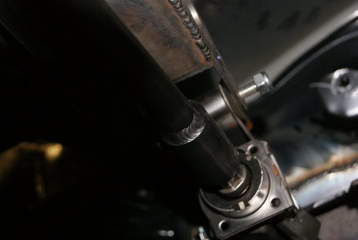
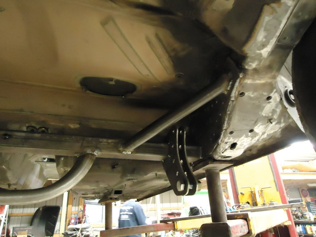
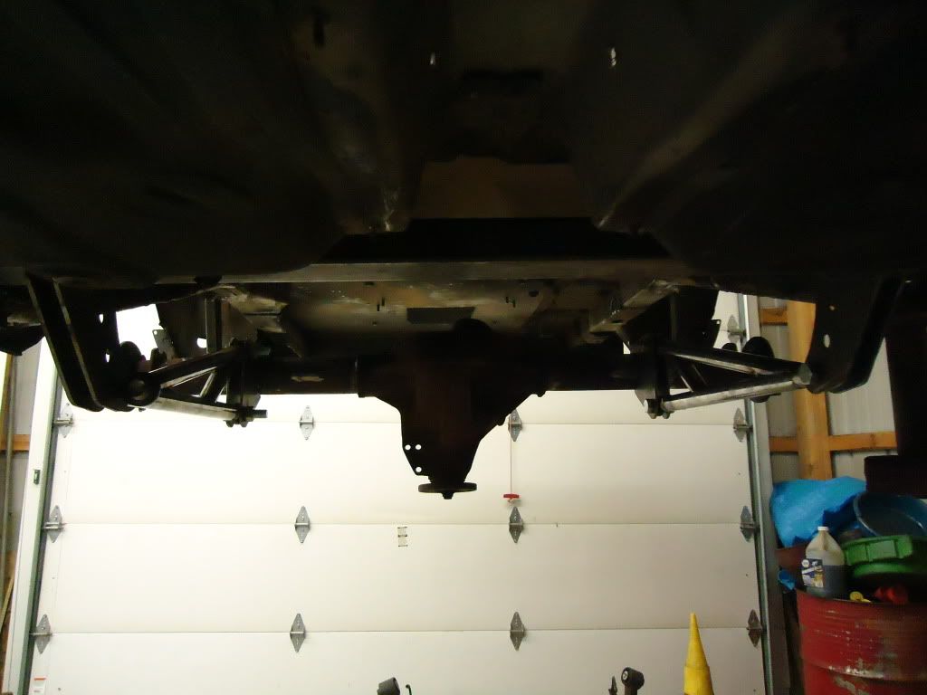
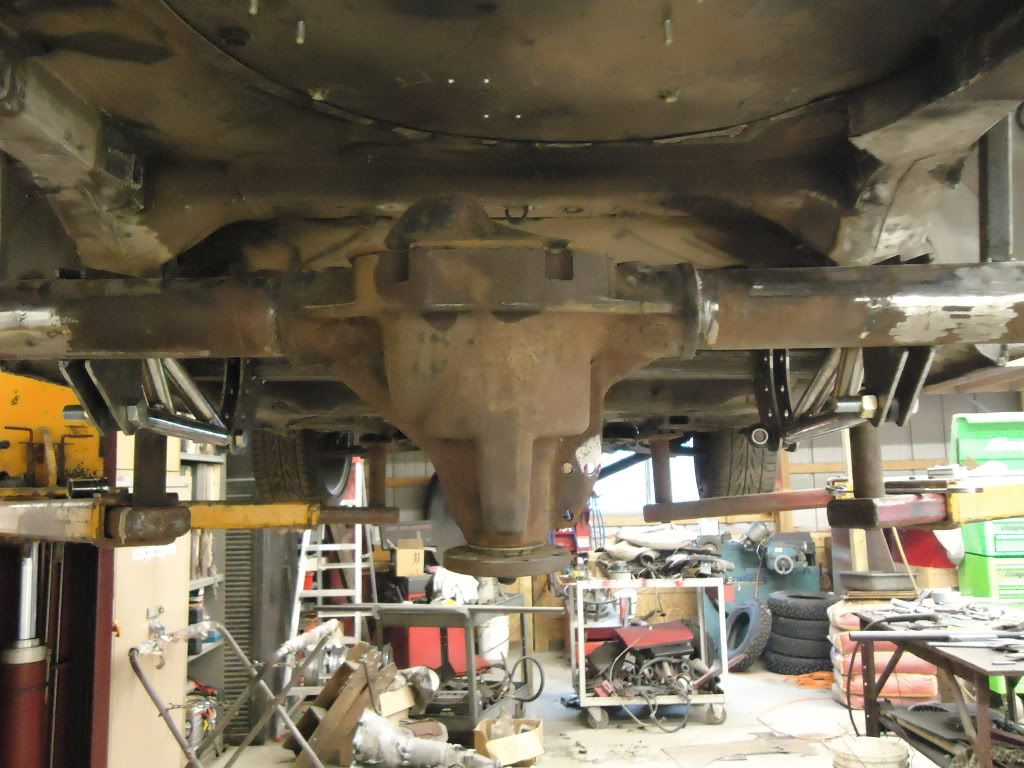
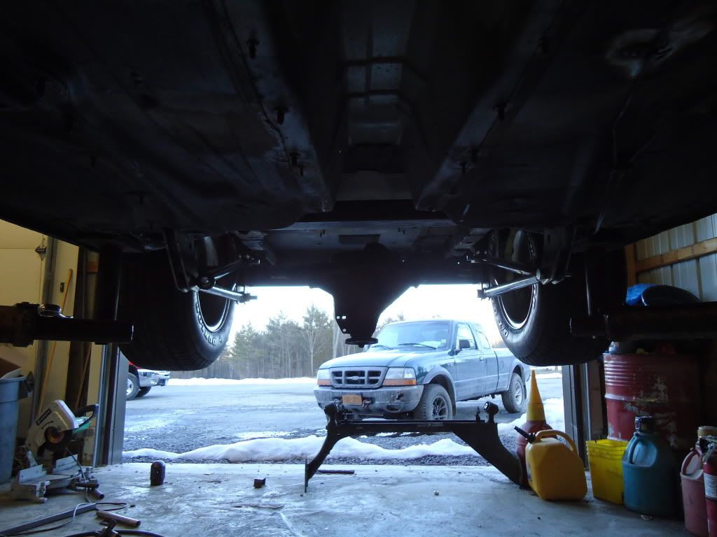
Then Mike cut a 1/8" plate the shape of the inside frame rail where we would mount the forward cross member to and drilled out holes for plug welds. Tacked it in place, and worked the plate left to right. Welded it an inch, beat it flush to the frame with a mallet, filled in a plug weld, beat it more, plug weld, 1" bead at the edges, hammer, plug weld… until it was all tight against the frame and fully welded. 2X3 3/16" wall tube was cut and positioned between the frame rails. Tacked the brackets and ladder bars up and positioned the suspension up perfectly. Added some 1.5" .120 wall tube diagonal supports to take some of the load off the 2x3 and disperse it over more surface on the frame rails. took 2 pieces of 1.5" tubing and bent them into 180 deg hoops, then welded them side by side to the 2X3 for drive shaft clearance, later we will cut out he 2x3 in the middle and weld on some end plates to finish it off.
Added the diagonal braces and the drive shaft clearance. Lowest part of the brackets are still 7" off the ground at ride height. Fully compressed suspension they are 2" off the ground.
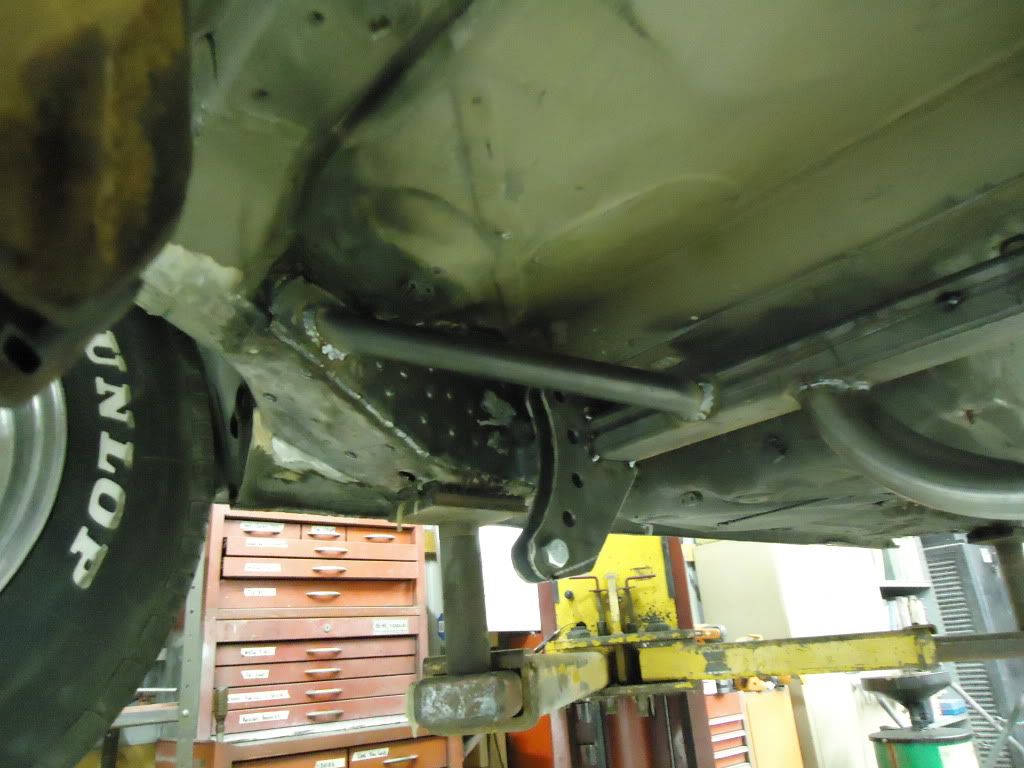
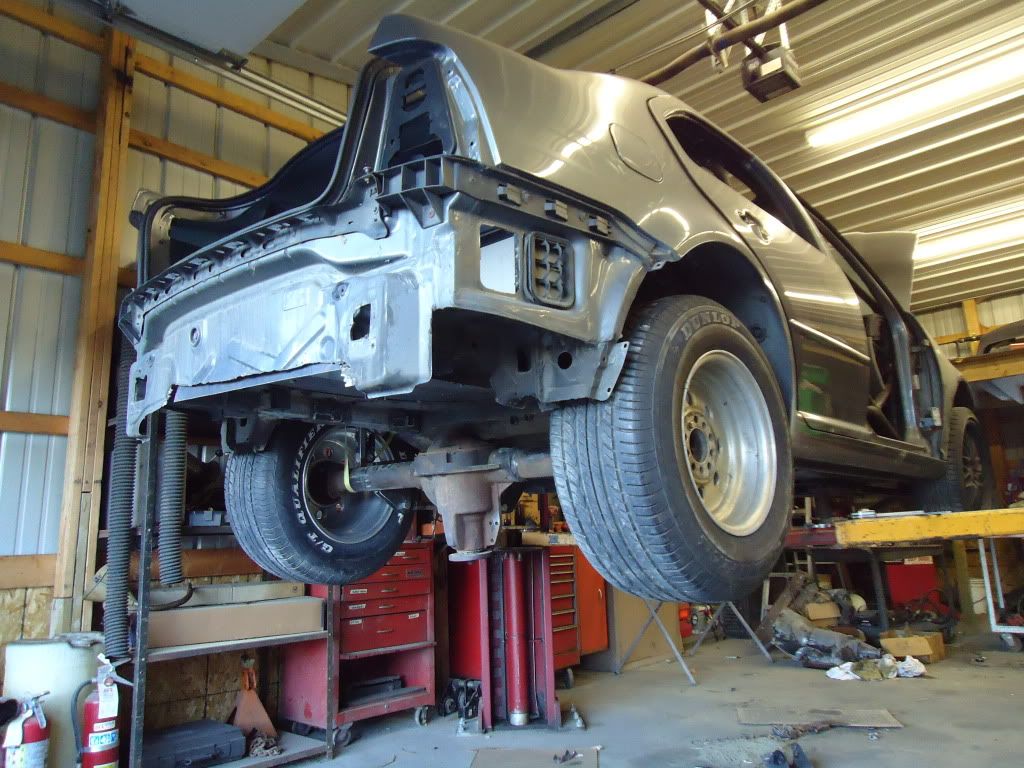
This shows the clearance on the 29X11 tires! Fit like a glove, and actually could go a little wider or use some spacers to get them out a little more. Keep in mind this is about 2 inches higher than ride height. Its set with the front suspension and the bottom end of the motor in place, so just about full droop because of the lack of weight. I wish I took a pic of the big tires stuffed up in the fenders! the tread rolls in from the sidewall and actually looked like the euro stretched and dumped look, tucking the tires up almost to the rim! :ahh
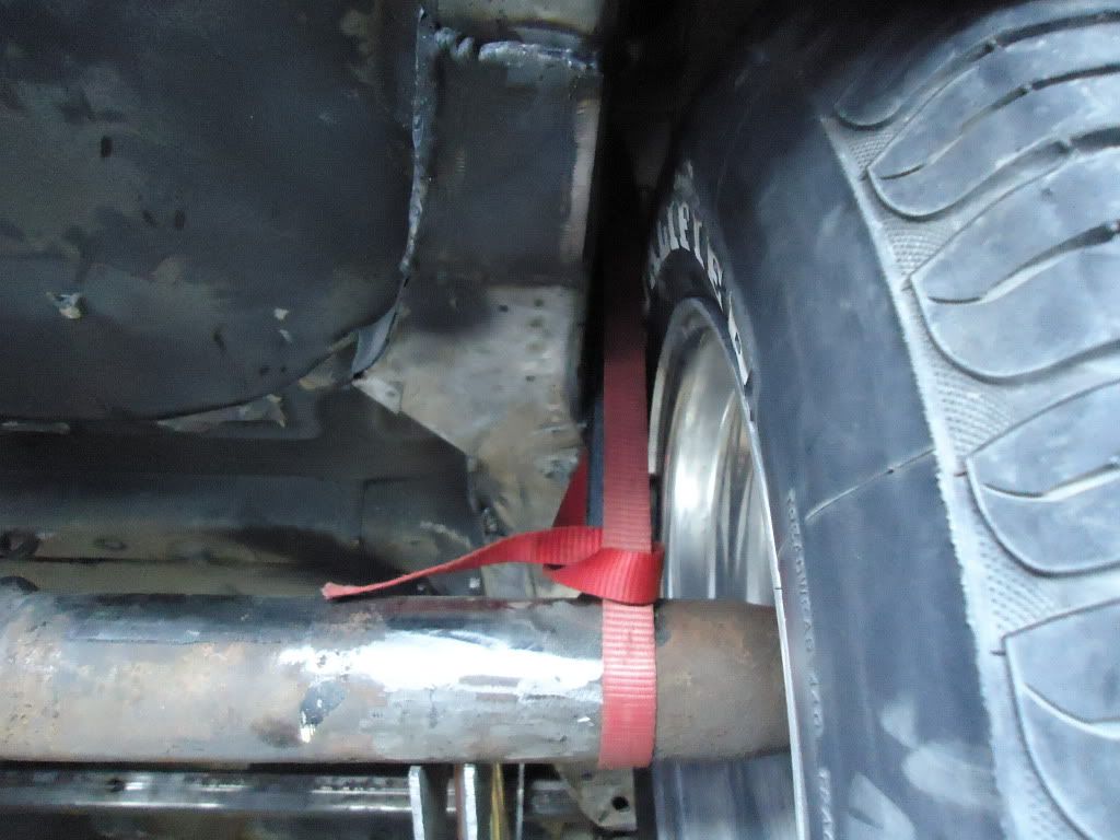
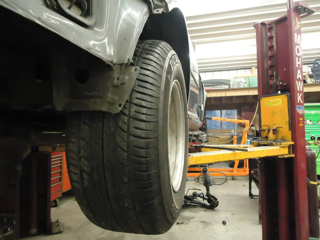
Dont mind the pinion angle :lol. It doesnt matter at all, we needed axle center to mock this all up. Once the coilovers are mounted and the ladder bars painted, correct bolts are used, motor and trans are in, etc. then we can measure for a drive shaft. Get that and set the pinion angle then.
Still to come is taking a small hump out of the trunk floor for the pumpkin clearance, and making a hoop for the coilovers to mount up inside the trunk a little bit, then sheeting it back in nice and clean. Sofar, there is NO major frame modifications at all to the shell! Just plated it in at key points and cut off unnecessary brackets.
Now on to the front suspension. We got all the stuff out of the way and off the car to look at what we can do.
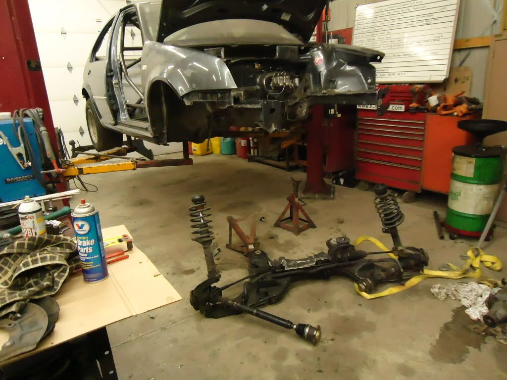
Made a halfass’d adapter plate to bolt the Powerglide to the 1.8T and roughly place it in the engine bay to see what we are working with. We laughed for about 10 minutes looking at the block and the transmission. The Powerglide, (one of the smallest domestic transmissions) is about 4 inches LONGER than the entire block and about twice as wide! Even with a head, and manifolds it will dwarf the motor! lol
This is just the body dropped over the transmission/block. No cutting yet. The valve body is about 4 inches lower than bottom of the floor, so we dont need to cut out a ton of the firewall we think.
The current idea we have is to make a tube cross member, to use the original control arms, struts and all. Get a small manual steering rack, and tuck it in the mix somewhere. The steering is going to be the hardest part so far I think. Also motor height is still up in the air. Do we want it low, keeping the CG lower, or higher, to shift the weight to the back of the car harder once it launches? Still thinking.
[SIZE=4]Stay tuned for updates! There will be plenty of long nights at the shop coming up soon. :thumbup[/SIZE]