heres some stuff to build ur own o2 simulators
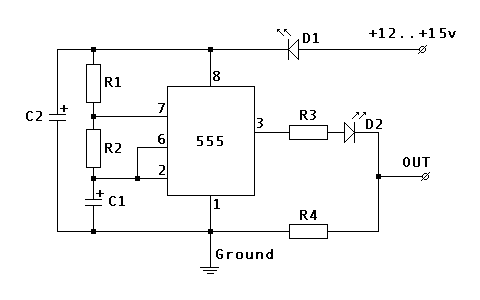
the diagram and parts list im posting is for a single output sim
but if u replace the 555 timer chip and use a 556 chip u can run 2 outputs for a car with dual downstream 02 sensors or u can just build 2 single boxes
all in total if u buy all the parts from radioshack the total cost will be 18.53 to build one
if u dont use the leds in the diagram u can save 3 bucks, but it will require adjustment of the one resitor on the output line
ok heres the diagram
this includes the leds but u can eliminate them if u like

r1 and r3 = 100k ohm resistors
r2= 1m ohm resistor
r4= 10k ohm resistor
c1 - 4.7 uf capacitor
c2 = 22uf capacitor
d1/d2 are 1.7 volt red leds
now with this setup if u have 4 wire o2 sensors u will need to leave the heater circut hooked up on the o2 sensor or the ecm will throw a heater circut open code
but here is a redrawn diagram that will make it able to replace the o2 sensor completly in a 4 wire o2 application
also this is redrawn without the leds so u will have to use a higher value resistor on r3 to get the output voltage correct
i dont recall the value off the top of my head so i will have to get it for u guys later on
in this drawing r4 will have to be the same value as the resistance measure over the 2 white wires of ur o2 sensor which is the heater circut
so basically u would just ohm out across the 2 white wires on ur 02 sensor and put a resistor with the same value as what u come up with in the r4 spot

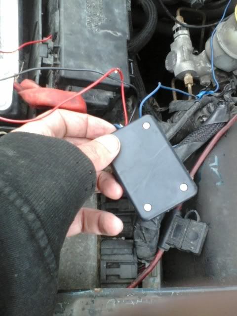
this is what one without the heater circut looks like when done ( one with a heater circut would just have one extra wire comming out of it
enjoy and if u have any ?'s just ask
