LS11111111111111
Richard stopped by on his Norton today while I was tearing into the Fiero. Hah. Nice to meet you.
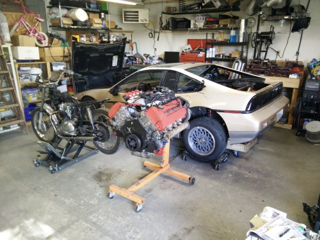
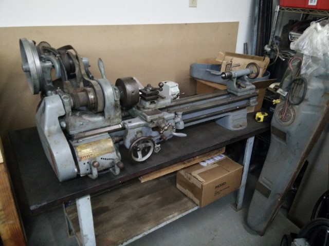
Anyway, I cleaned up my side of the shop, shoved the Fiero in the corner and ripped out the motor. I also dug out a hole next to the Dalton for a nice South Bend 9A I’m picking up next weekend. Even though I love it, I won’t really need the Dalton any longer. Would anybody possibly be interested in it? I’m about 50% on selling it.
Here’s how I’ve got stuff set up so I can work on both toys over the winter. South Bend goes to the right of the Dalton. Everything is on wheels and can move if it really has to.
…and then I decided to drain the oil out of the Northy just for funsies. Here’s what I found in the filter:
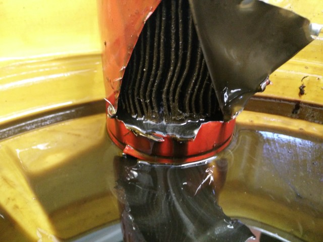
Awfully shiny in there. Looks like I’m dealing with [a] bad bearing(s). I think I caught it before it got super bad, so maybe there’s not a whole bunch of damage. Hopefully it’s not a spun main bearing so I don’t have to replace the block. If it’s just bad rod bearings, I’m in okay shape. I’ll machine the rod journals on the crank, replace all of the bearings, put in forged rods and forged pistons, and then get a high-RPM rotating assembly balance. So probably around $2,500 or so. Could be worse. Depending on funds and time, I could also end up with a dry sump oil system and/or t3h turbo. We’ll see.
I’ll find out for sure once I tear it down. I think I’m off next weekend too. Maybe then. After I pick up my South Bend.
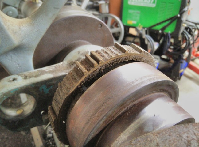
Just for funsies, I decided to take apart the clutch and see what was in there. What the fuck is this shit?
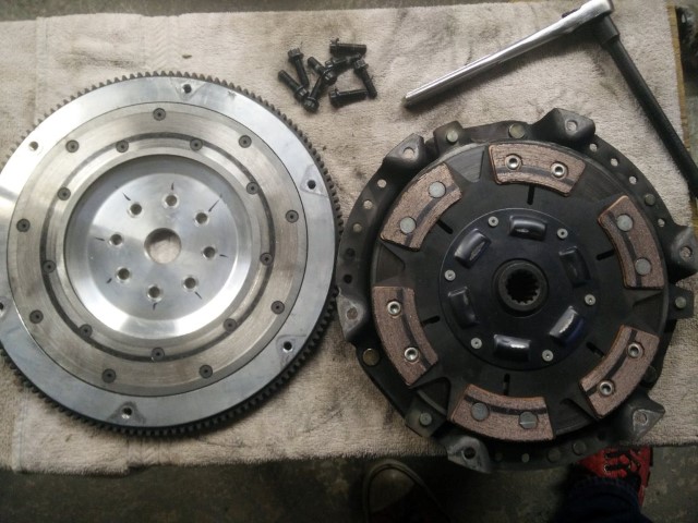
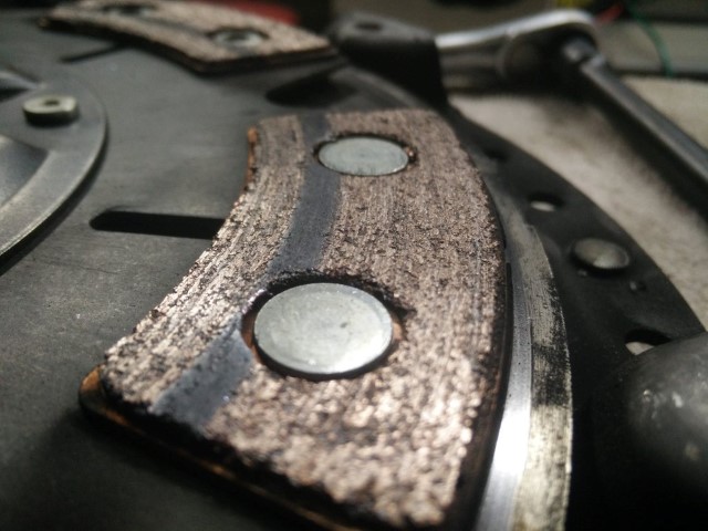
I can’t tell exactly what’s going on, but there’s a 1/4" or so section of the disc that hasn’t worn in properly and there’s a corresponding mark on the flywheel. Something isn’t quite right there. Maybe the pressure plate is fucked? No matter. I’ve moved on.
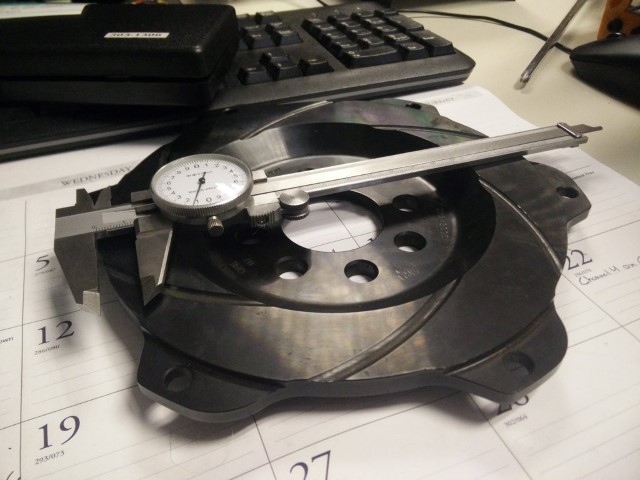
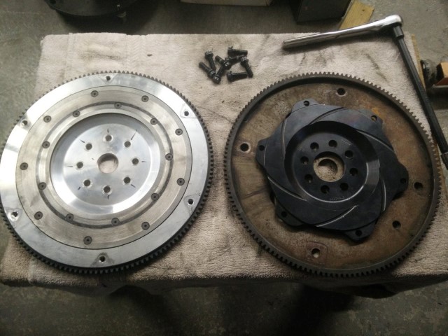
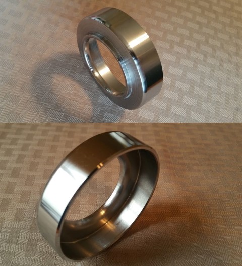
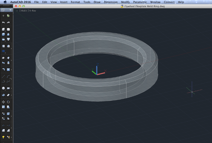
It’s a QuarterMaster 7.25" flywheel drilled and bored for a Mopar R5/P7 motor, and I got it for $40. I’ll be stacking a twin disc Tilton OT-II cerametallic clutch on top of it. It’s a button flywheel, so it’ll stack right on top of the factory flexplate and I’ll still be able to start the thing. I really need to clean it up, though. With the pressure plate and diaphragm springs I’m planning to order, I’ll have about 580ft./lb holding capacity.
I also picked up my new [to me] South Bend 9A; got it wired up and tested. Seems to work just fine with the VFD. I set it up for to take 5 seconds to accelerate to full speed and 3 seconds to decelerate. It’s pretty rad. The included three jaw has about 5-7 thousandths of runout right at the jaws, but it also came with an independent four jaw, so I should still be able to get things pretty damn true.
Anyway, I’ll need to make a few things with it to get this flywheel on there. Namely, I’ll need to make a drilling/tapping guide for the crank snout so that I can upgrade the existing tiny M8 hardware to M12 hardware at the same time I move the bolt circle inwards a few millimeters. I’ll use the same guide to open the bolt holes on the flywheel. I’ll also want to make a concentric adapter to go into the crank pilot hole and make sure the flexplate and flywheel stay centered. Finally, I’ll need to make an adapter that slips onto the hydraulic throwout bearing that gives me the recommended 44mm contact surface for the diaphragm spring fingers. Here’s one somebody else made. I’ll have to make a a similar one, after I measure clearance between the fingers and throwout bearing.
Oh, and that motorcycle thingy, too. Still need to get to work on that…
:bigtup:
I wonder what caused the friction surface to wear like that. Did a piece of something get sandwiched in there and rub until it got burned up and spit out?
Sure looks that way. I noticed that there were gouges in some of the rivet heads on the clutch disc and it looked like the friction material was sort of ‘flaking off’ around the rivet holes. I was very disappointed to see that when I pulled the disc off of the flywheel. I’ve got like $600 into even that clutch. Pressure plate side looks fine, strangely.
I don’t think I need to have custom friction discs made, either. The F23 transmission I use claims a 1" shaft with 14 splines. Tilton actually sell 14 spline discs on a 25mm shaft diameter. I know it doesn’t sound like much, but I was actually pretty worried about the .4mm difference. That’s 16 thousandths. Anyway, it turns out that the shaft isn’t actually 1" [25.4mm]. It’s pretty much spot on 25mm, so the discs should fit. I’m pretty sure I’m not the first to try and use this clutch in an F23, but I am the first to use this flywheel setup. Should help this little bastard rev even faster.
Had to work all day today. Still not done. Kind of bitter about it, but no matter; I got all of this stuff figured out.
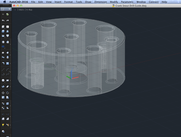
So. Here’s the guide that I’ll use to redrill the crank snout:
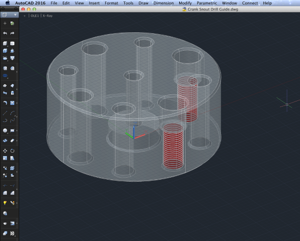
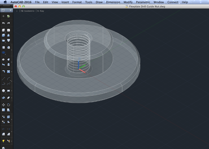
I basically stole the idea from the head stud jig. It centers on the crank pilot shoulder for precision. It will allow me to drill two holes then be flipped so I can tap those two and drill two more. Then I flip it back and tap those two holes, rotate the whole jig 180 degrees and do the other four the same way. Two bolts keep the jig torqued to the crank at all times. The two tapped holes are counterbored to 15mm at a depth of 15mm for clearance and are used to guide the tap into the crank snout. The same guide will be used to accurately drill the flexplate and new flywheel. Here’s the adapter for centering/clamping the jig onto the flexplate. I’ll knurl the outer diameter just for funsies.
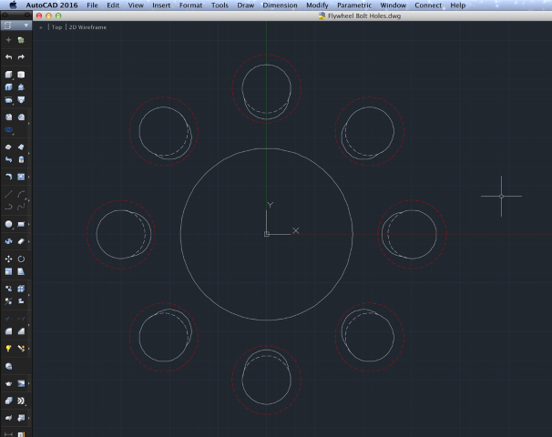
I drew a similar adapter for the flywheel, but that looks pretty much the same; kind of uninteresting. Here’s what the ‘siamesed’ holes will turn out to look like in the new flywheel. The new holes are 12.5mm and will be chamfered. Anyway, the new ARP M12x1.25 hardware torques down to 110ft./lb., so I’m not worried about anything happening in the future. The proposed hardware heads are in the render down below in red. There is still some traction all around the underside of the bolt head. Glorious! I’ll also draw/make a centering adapter for the flywheel/flexplate/crank snout to keep things rotationally happy. I just don’t have the critical measurements yet, so I haven’t done it. Anyway, here’s this:
Not ideal, but not really a problem.
I’ll probably start working on this next week.
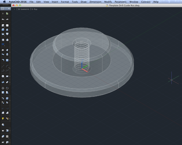
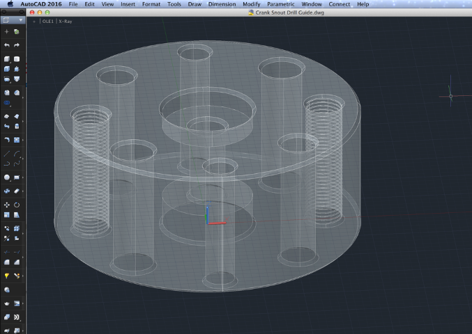
I decided to change that drill guide around. I wasn’t in love with the lack of symmetry and the fact that the two bolts holding it to the flange were only 90 degrees apart. I fixed that. Now the holding bolts are located 180 degrees apart and fit both sizes [original M8 and new M12]. I also enlarged the center hole to M10 so that I can really get some torque on the nuts to hold everything together. I’ll make the nuts out of steel and then maybe machine some vise flats into them as they’re too large for wrenches. The guide body I feel can be aluminum. Should I think about anodizing it for wear/friction reduction? I suppose it’s really just a one use thing and I can probably fairly successfully oil it a bit to get through.
Here’s the same flexplate nut from earlier with the larger M10x1 thread.
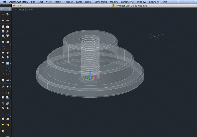
…and here’s the flywheel nut just for funsies. Again; the nuts will be steel.
It occurs to me that I’ll need to make a holder for the tap to make sure that I tap the guide properly to begin with. The size of that will depend on the size of the tap. We’ll know more when that shows up. I’m pretty hopeful, anyway.
I’ll have to go raid Metal Supermarkets’ scrap bin on Monday.
EDIT:
One more for tonight.
Based on the tap set I bought, I’m getting rid of the counterbore and adding one on the bolt side at the pilot hole. Mainly just so I that I can flip the guide over if necessary.
Also, it occurred to me that the flywheel centering ring doesn’t need to be terribly complicated. I’ll cut this out of steel, center it up on the steel flexplate and weld it on at that internal chamfer. So then the flexplate centers on the crank snout, and the flywheel centers on the flexplate. Boom. Done.
I need to go to bed. Maybe I’ll get to play with this a bit on Monday.
“I need to go to bed. Maybe I’ll get to play with this a bit on Monday.”
That’s what she said.
TV Show “Car Fix”: Season 5 episode 11 they throw a northstar into a Fiero.
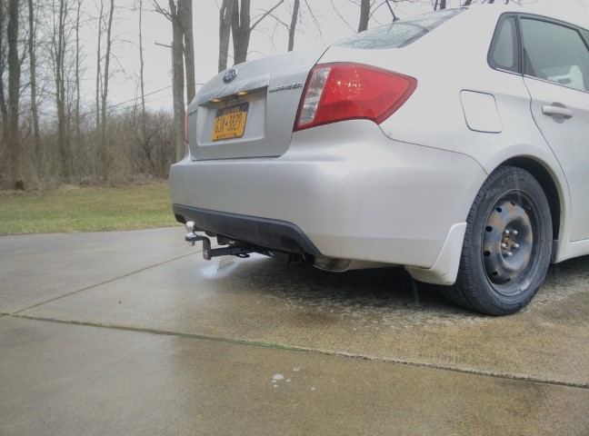
So, I’ve been pretty jammed up at work lately and I haven’t had time to really even think of the Triumph. If I’m honest, I’ve got a good several months left of build time on that and a bunch more money to spend. I want a toy this summer, so I decided to get back to work on the Fiero for a few weeks. I decided to start with a ‘new’ bottom end, instead of dicking around with rebuilding right now, so I bought another 4.0L with ~80K. I ordered a trailer hitch for my Subaru, hoping it would be delivered by Thursday morning. It was, so I installed that.
Pops had a freshly painted car door propped up against a ladder inside the shop, so I had to work outside. I finished before the sleet.
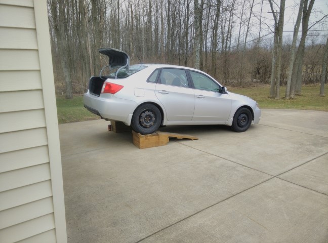
Tow pig.
Borrowed a small motorcycle trailer to go pick the motor up and dragged it back to Eden.
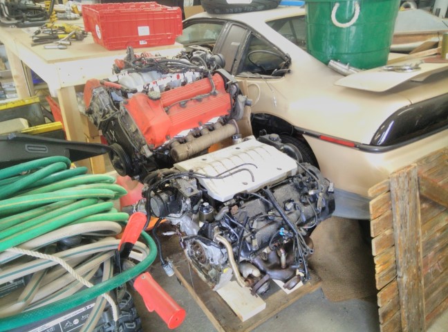
I’ll spend a day or two in the very near future taking the heads off of both motors, repairing the head bolt holes and replacing the timing wearables in the new one and finally, putting my ‘built’ heads on the new one.
Then I just need to address my clutch issue and a few other miscellany.
Oh, and I decided to investigate why the back gear on my South Bend didn’t work as I’ll need it for threading work. Found this when I pulled the covers off.
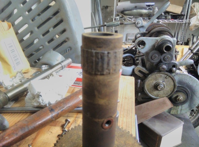
Cool story. I can get a good bull gear for ~$50 and a back gear assembly for ~$100, so no huge deal there. I’ve also found a good amount of backlash and general sloppiness all over the machine, so I’ll likely take it apart to rebuild it very soon. I’ve ordered some parts to do that. Needs to be at least adjusted before any real precision work.
Oh, and I got to the bottom of my ECM issues from last season. Found these when I took the computer apart.
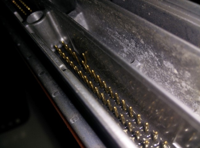
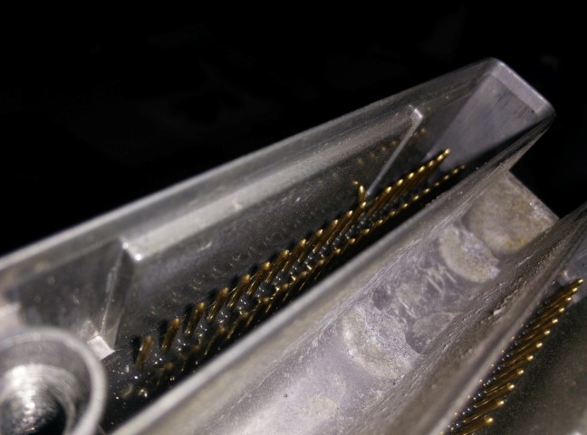
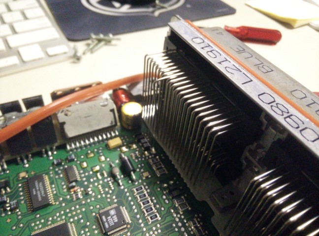
The last two are the same pin. That one was the MAP 5V reference. The first one was IAT signal. It was pressed ip against the case of the computer, shorted to ground. Explains the high temp readings. Should run a bunch better this year.
Should be ready by the end of the month?
Nice work finding the electrical issues, luckily it’s an easy fix.
I like this build!
I love everything about this, can’t wait to see it together.
Glad you’re back on the horse
Hah. Thanks, fellas. I managed to straighten the pins out and make everything work with a spare set of connectors I had lying around at the shop. Obviously haven’t tested it yet, but the one ‘missing’ pin explains my lack of MAP signal because it didn’t have the 5V reference and the pin shorted to the case explains the ~300 degree intake temps as GM IATs drop resistance with raising temps. Doesn’t explain my VSS issue, but I suppose that could genuinely be an HPTuners configuration issue? Guess I’ll find out when I get a motor back in it.
I bought all of the materials to make my crank flange re-drilling jig as well as the necessary bits, taps, bolts, etc. to complete the project. I’ve got a factory Northstar flexplate which I’ll sandwich between the button flywheel and crank flange, so I can retain the starter gear. Just need to make that drill/tap guide and I can get to work on the crank.
I also need to reseal the transmission as that was leaking from the case half seal. I’m pretty sure I used Permatex Anaerobic last time I put it together so maybe I’ll try something different, or I just didn’t do it properly. I’ve read good things about ThreeBond 1215, Permatex 599 Ultra Grey, or even Yamabond. They’re all RTV silicone. Just have to be careful to not use too much, I suppose.
I’ll spend a day or three cleaning up the engine compartment; mainly re-welding some things, adding some gussets and finally painting it. Then I’ll work on getting the decklid back on.
Where does this thing fall in the cars and coffee parking arrangement?
I’m genuinely curious of the same. I haven’t been to one yet, but I’d like to bring this. Not sure if it qualifies as a “participant,” though, I’m not sure I care. I can always just park in the “normie” parking and walk over to the show. No big.
I would think this car is known enough to the point it can find a home in the lot no prob.
this 100% should be in the show
Jr and I are very disappointed in your decision to put the Triumph on the back burner and resume this.
Did you use the primer before the Permatex anaerobic? Ive had good luck using this on my cavy transmissions.
Dan