Hah. Listen. Trying to find/buy a house with my girl and working 70+ hours a week isn’t really affording me any real time to work on it anyway. Plus, I’ve got to tear down my lathe and rebuild it so that it’s not sloppy and cuts somewhat accurately. This should be a relatively painless in-and-out. Should be done by the end of the month. Trust me, I didn’t want to go this route, because the Triumph was already supposed to be done. I’ll find time for it this summer. Life slows down a bit for me then.
I did! But if memory serves, I used it on both halves and then after reading the instructions [which is always the correct procedure], I realized I should have only primed one. Perhaps I should just try it again. I believe I’ve got more primer. Does the primer expire? I imagine the sealer itself does. I think I still have the tube. I’ll check tomorrow.
Hah. Not exactly. I make a bit more than her, but she’s waaaay more frugal/responsible. She did the first time home buyer’s thing, so she’ll get an extra ~$7,500 from her bank. Can’t really complain about that. We wouldn’t qualify for the program if we applied jointly. Only trouble we’re having now is that she isn’t approved for a substantially large amount, so we’re struggling to find something decent. Not sure that I’ll get the shop that I want, but I suppose I can build one if we stay for a while. Who knows? I think 1.5-2 cars should do for now.
From what I’ve read, people hold products like Hondabond and Yamabond up on pedestals. Really, any sort of oil resistant ‘gasket maker’ should work. The trans takes ATF, after all.
I probably just fucked up the original application of the Permatex Anaerobic, so the damn thing leaked.
Also, in cross referencing several service manuals and online forums, I discovered that most of those import ‘gasketless’ sealers are simply just Permatex Ultra Grey. Might try some of that. I’m pretty sure that’s what I used to reseal the engine block case halves and those weren’t leaking…
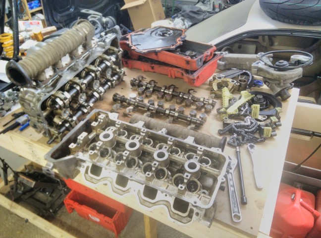
Started taking apart the old motor today. Basically got it down to the shortblock. I really wanted to peel the bottom end apart today, but I got there late and didn’t have enough time. Oh well. Next time.
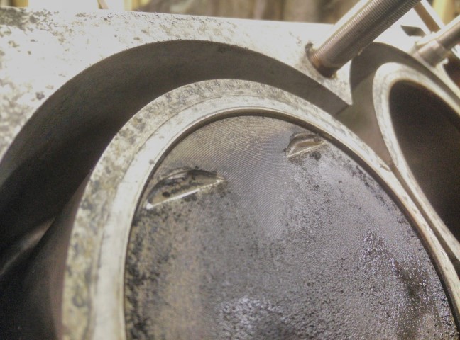
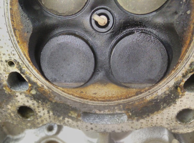
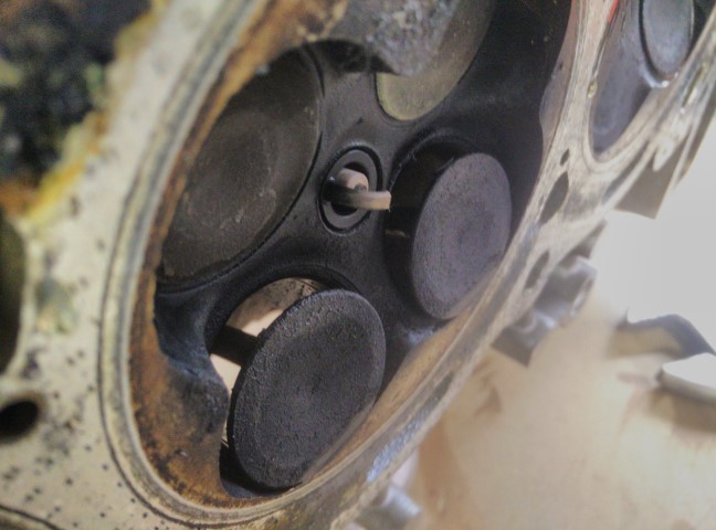
Anyway, when I pulled the heads off I found this evidence of something pretty gnarly.
Then I had to disassemble it.
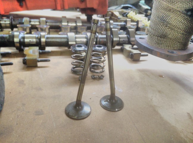
Oof.
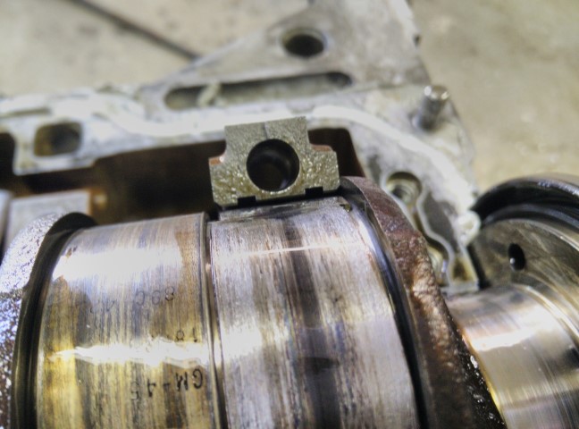
My theory is that I’ve found the cylinder with the toasted rod bearing. Basically, the failed bearing allowed the pistons and valves to come together and the valves didn’t win. Hopefully the guides aren’t toast. Hate to have to replace them if I don’t have to.
I thought about it some more, and I’m pretty sure I did that valve damage myself when I was taking the motor apart. I think I got excited and disconnected the timing chains before I pulled off the balancer pulley, so the crank spun independently of the cams. Whoops. Never said I was a genius. Brand new OEM intake valves are $7 each and I’ll just lap those two in for now after a good cleaning. Kibblewhite will make me custom C630 bronze guides along with their own proprietary powdered metal seats and Manley [among others] will make me valves. Should be able to put together some really nice turbo heads down the road.
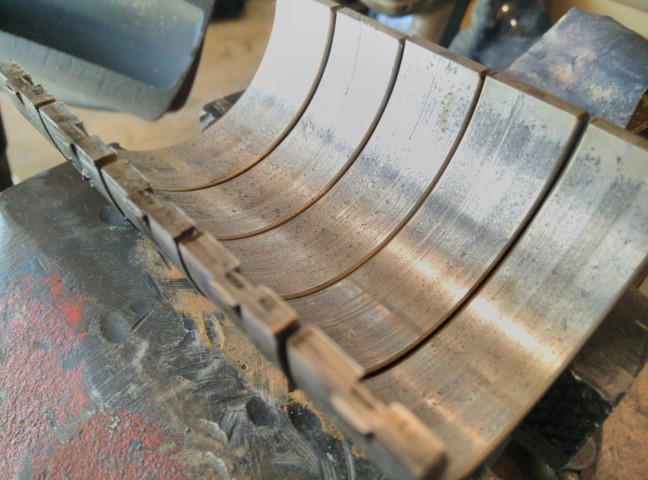
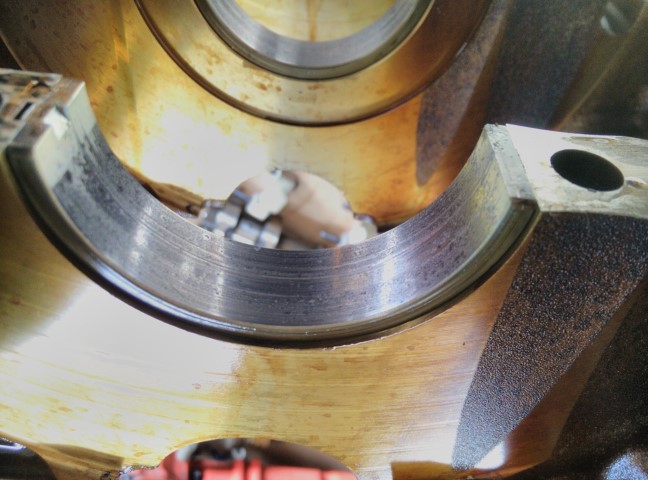
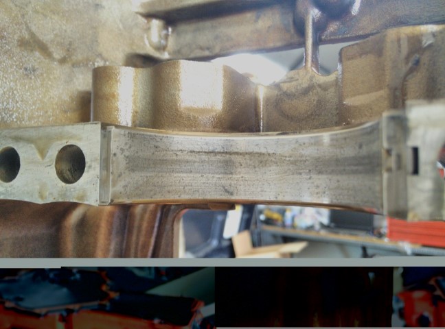
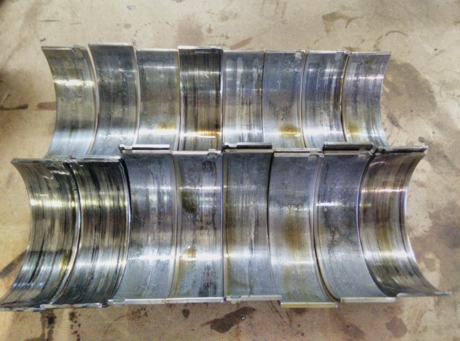
Anyway, I tore down the old bottom end today. Holy fuck.
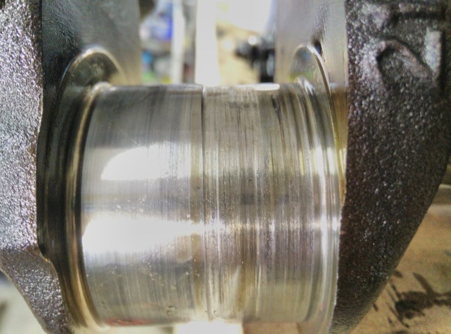
First, the mains. Worn smooth out from stupid high mileage no doubt and there are lot of gouges. I definitely lost oil pressure.
Could be worse, but not good. Anyway, onto the good stuff.
Straight carnage.
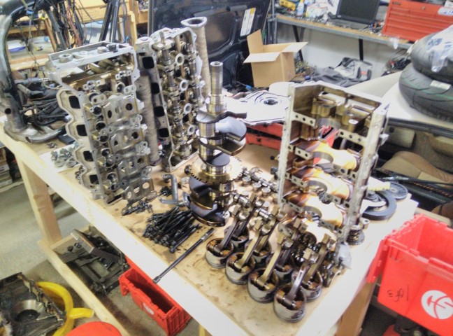
Damn thing’s got a shitload of parts, though. So now I’m going to bag & tag everything to go into a plastic container for storage until I’m actually planning to build this block.
Anyway, all I have to do for now is either swap valve springs between heads and or swap heads after I replace my bent-ass intake valves. I should probably just swap the springs. I don’t believe the new motor has ever been overheated so hopefully the heads/deck are pretty flat. I might have the old parts checked by a machine shop.
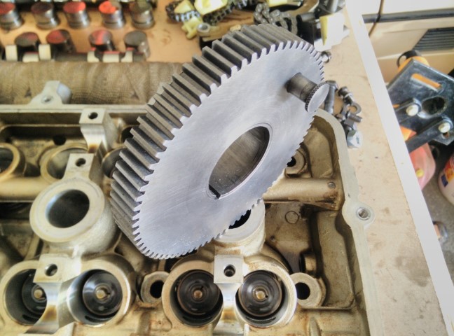
Oh, and I got a brand new-lookin’ bull gear for my South Bend. It’s pretty. Just need a set of good back gears now.
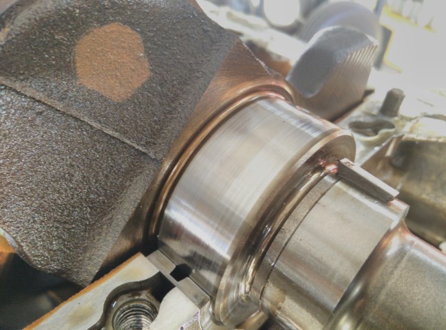
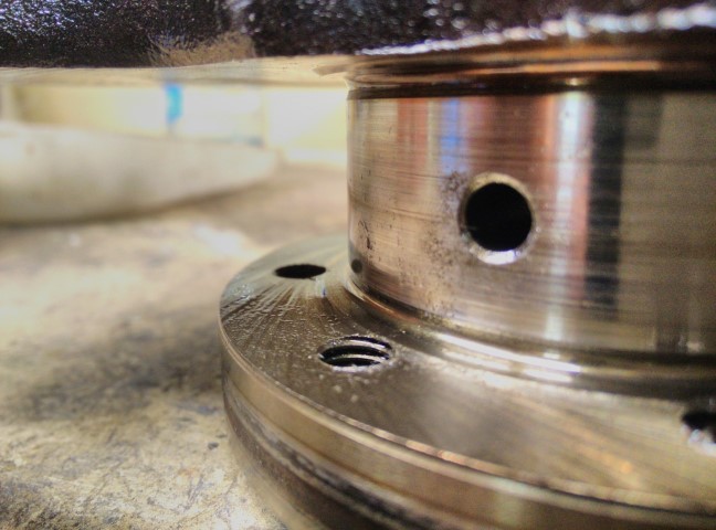
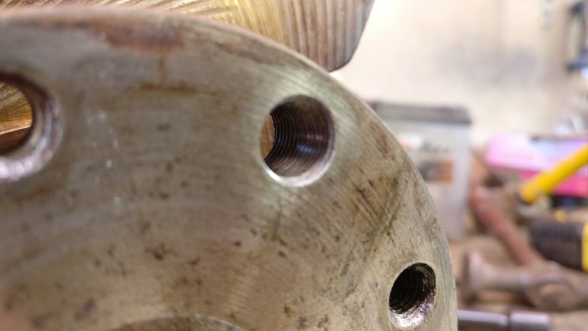
Took a closer look at the crank today. Moving the crank pattern and enlarging it ain’t gon’ work. The rear main journal is RIGHT there and there is only ~.073" clearance between the back of the crank flange and the main bearing bulkhead.
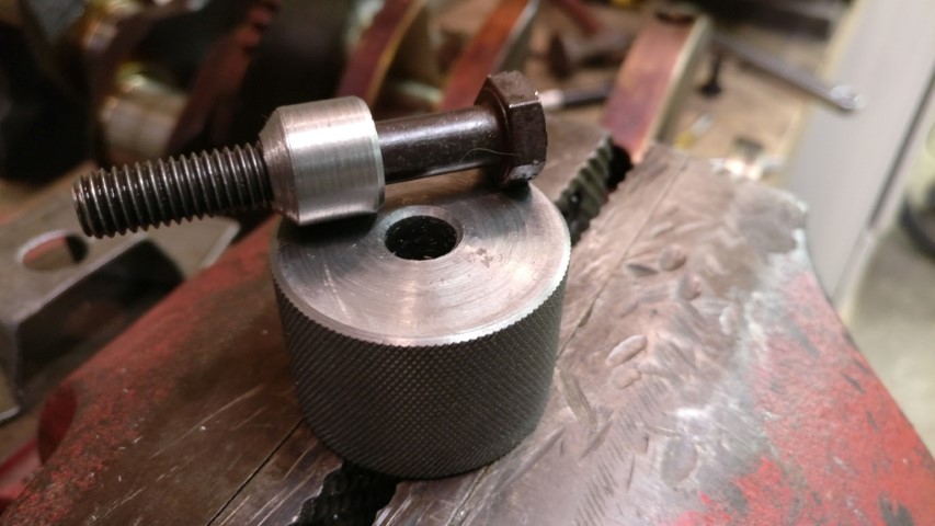
I’m accounting for .065" clearance between the bulkhead and crank flange as a hard maximum for the protrusion of bolt tips, even though indicated deflection with the thrust bearing in place is only like .002". Safety nets and such. I did a little math, and M10x1.0 minor diameter is ~.6mm larger than the existing M8x1.25 major diameter - i.e. all new threads are cut. A 9mm drill should bore out the existing holes and I’ll re-tap for M10x1.0. Plus, I’ll still have plenty of meat left on the crank flange and I won’t have disturbed the radius machined into the journal. I’ll now likely drill an entirely new pattern into the flywheel as trying to siamese the existing seems too much. The patterns are a fair deal different. Should I whittle up some plugs and autogenously weld them into the old pattern bolt holes with my TIG torch to try not to disturb balance too much?
I don’t know for sure, but it seems like a few of you are engineers. Anyway; I have a few thoughts about this flywheel.
Option 1.
I simply drill the new pattern into the steel flywheel, leaving ~.110-.125" of material between bolt holes and completely ignore the existing unused bolt pattern. Done.
Option 2.
I plug the existing pattern with lathe-turned plugs for a .003" press; pressed in along with Loctite 648 or Permatex Sleeve Retainer. I then drill the new pattern on top of the existing pattern, sort of siamese’ing the existing holes, but then; they’ve been press-plugged so I’m cutting into the plug and not ‘old bolt hole’. …or I simply plug and redrill the new pattern 22.5 degrees offset from the original as in Option 1, but this time the existing holes are plugged.
Either way, I can true up the front and rear faces on the South Bend and this is a neutral balance joint.
Thoughts?
I don’t mind the idea of the siamese’d holes after the press plugs because the plugs will not only hold tension on the bores, but will be held in place by the adhesive, washers or the factory flexplate washer plate and of course, the press fit itself. Then again; the plate over the offset holes would cover [retain] the plugs as well.
Which method results in an inherently stronger flywheel? Keep in mind this is a ~.305" thick steel, ~6lb 7.25" QuarterMaster button flywheel.
Are the plugs just an aesthetic thing? Do they really even matter?
…and if I ordered a clutch package [pressure plate, floaters, friction discs, etc.] from Summit or Jegs today it won’t apparently ship until the end of the month. Fucking drop shipping.
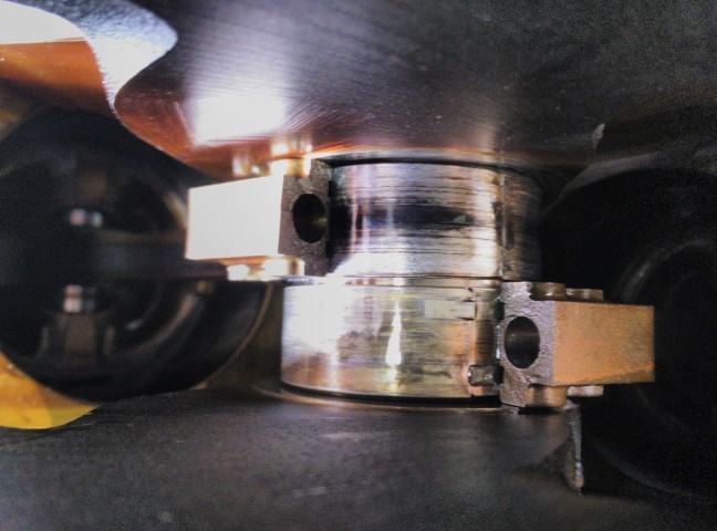
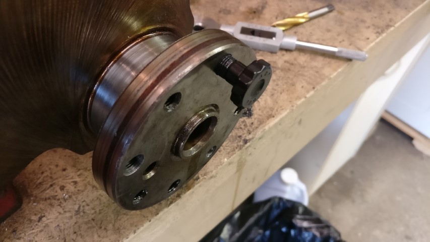
I worked on this a bit yesterday. Basically, I tested a few things out on the flange of the garbage crank.
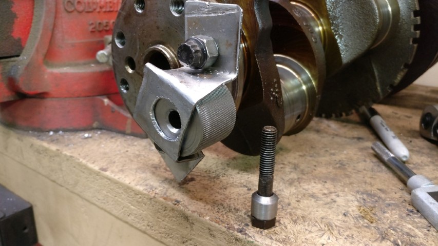
I made a guide block for the drill bit, along with a tapered sleeve for centering it about the crank flange hole. The tapered sleeve came later, after I realized I’d really need to clamp this tight to the flange.
I found out that I couldn’t realistically keep the bit straight while drilling with the guide, if said guide was loose. I bent up some ~12-14G steel to make an external clamp to hold the guide against the flange, but somehow I needed to center it on the bolt hole to be drilled and keep it there while I install the external clamp.
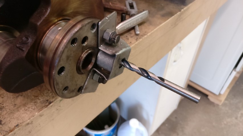
I tighten the bolt and tapered sleeve down into the countersink of the guide block, making the guide concentric with the bolt hole. I then install the external clamp, remove the bolt and tapered sleeve and drill out the hole. I still need to make a guide for the tap to make sure that goes in straight along with stop collars for both the drill bit and tap.
Nice, new M10 x 1.0 bolt holes. Seemed to work out pretty well by the time I was done ‘experimenting’ and working out a good process. I was able to use off the shelf ARP Ford Coyote flywheel bolts. They’re the perfect length. Now I just need to plug/re-drill the flywheel and reassemble the ‘new’ motor. I’m still waiting for my clutch to ship, but I ordered that on the 12th, so should be soon. I’m pretty sure I’ve settled on plugging the existing flywheel holes and drilling the new pattern 22.5 degrees offset. The plugs will be a .003"-.005" press with sleeve retainer compound. I’ll chuck up and face the back of the flywheel with the South Bend to make a nice, true crank flange surface. I can also check for runout and correct any issues there at the same time.
Don’t they make a flywheel with the right pattern? in my opinion, fuck drilling the crank trying to align all this nonsense and risk another crank and just punch fresh holes in the flywheel… No threads, no plugs and nothing is going to leak out of the flywheel if there’s extra holes.
Nobody makes a flywheel for this application. This motor never came with a clutch from GM, much less a twin disc. SPEC makes a single disc aluminum flywheel, but I already own one and it’s got a weird issue with the friction surface and ClutchNET disc that I’m not happy about. I’m not really interested in trying that again.
The reasoning behind the bolt enlargement is that there is no such thing as an M8x1.25 flywheel bolt. They don’t exist. And even if I had ARP make me custom bolts, they would still only torque to ~35ft/lbs. That’s not enough for a flywheel. The M10x1.0 bolts torque to 70ft/lbs and are real, actual flywheel bolts.
There’s really no ‘risking’ a crank here. The first crank is garbage from three fucked rod bearings that ate up their journals. The guides keep the drill bit and tap nice and perpendicular to the surface.