Is this any better? Something else in which to put an Aurora/Northstar?

Is this any better? Something else in which to put an Aurora/Northstar?
I wish it was, I was hoping one of you guys grabbed it.
It appreaded to be very nice. Well worth the money.
Glad this thing is tearing up the streets.
Indeed. 'Tis rather enjoyable. It loves to accelerate what with the new flywheel/clutch setup. It squeaks. Holds like crazy, but it squeaks. It’s kinda funny.
What a freakin’ goofy car.
Even used it as a grocery getter. Love the looks I get as I literally fall into it.
…and I found the source of all of the schmutz all over everything. Passenger CV boot is ripped. Rad.
…and something is rattling like hell at low speed in high gear. i.e. highest engine load. I can’t tell if it’s in the engine or transmission. Inside the car, it sounds like the engine and outside, it sounds like the transmission. I’m just not sure. Doesn’t seem to be impeding anything.
Needs a tune. I know I keep saying that, but it really does. It’s pig rich and I don’t know what I’m doing enough to do it myself. I was thinking about taking it up to New Era. Do I get a discount for owning my own HP Tuners interface? Hah.
Here’s what it sounds like:

They were dirt cheap. I couldn’t resist.
Now you can tune it yourself
Almost didn’t make it home today. I did. But I almost had to give up.

Sketchy AF. Really need to get those ceramic PTC elements and fans in there.
Here’s a video I caught of me dropping in the sunroof and attempting to outrun the rain.
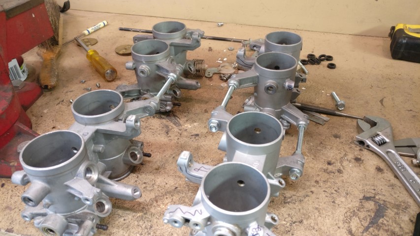
Wasted some time on the ITBs today. Hah.
So here they are after I pulled them out of the box and stripped them of most of the unnecessary stuffs.
The primary [lower] throttle blades - 40mm, which according to popular ITB references, should support 50-56bhp per cylinder at 500cc displacement per cylinder. Perfect!
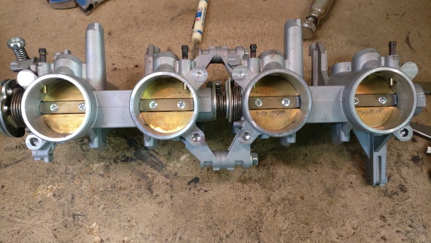
And the secondary [upper] blades - 45mm, which were removed. They’re for low-speed engine stability and prevent choking the engine with too much air at once. They’re not necessary on the car, so they’re gone.
I had trouble getting the screws holding the butterfly valves to the shaft broken loose on the secondary blades, so I drilled them out instead. Much better. I’ll have to plug the holes in the sides with appropriately machined aluminum plugs. Pressed and welded, of course.
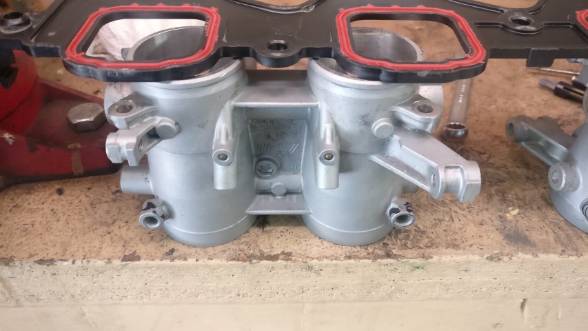
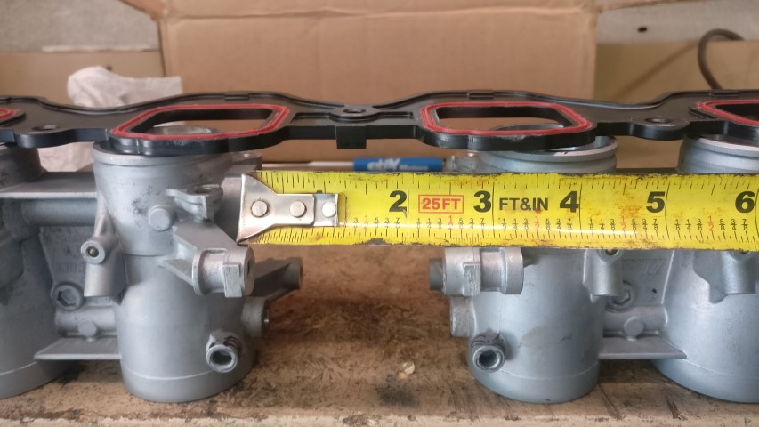
So these units are a bit tougher because instead of being four individual units attached together, they’re a pair of two, joined in the middle. The bore center offset is approximately .603" at each bore or 1.205" for each pair. Clearly visible.
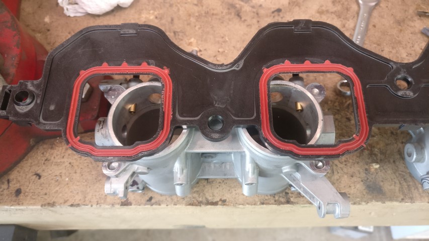
…and the gap between the pairs required to at least center the TB pairs over their respective ports.
I calculated using various sources that a ~1.5" tube runner will give me a ~5,100RPM torque peak, and a ~14" runner length will allow peak power to be built about 7K. The intake port to back of intake valve is ~4.5", and the TB is 3.5". That gives 8", and with a 2" velocity stack leaves ~4" for transition from head to bottom of TB. Can do. Might have to hand form some custom elbows out of sheet metal, but I’m into it.
Looks like the factory throttle blade shafts are 10mm. I’m going to machine two fittings that attach to the inner end of each TB ‘unit’ and attach together with a short piece of 10mm shaft. That shaft is the perfect place for a 50T steel spur gear driven by a 15T steel pinion, for a 3.33:1 reduction. This will be further reduced by another 50T/15T combo to a NEMA17 stepper motor, for a total reduction of ~11.11:1. I bought five Matsushita NEMA17 motors that claim 76oz/in holding torque, I’m guessing in a bipolar configuration. Only really need the two, though. Unipolar configurations don’t seem to have the same holding power, though the electronic drives necessary are less complex. Interfacing H-bridge motor drivers to Arduinos is a pretty easy task, so I’ll go bipolar drive for the speed and torque benefits. That 76oz/in is .537Nm and into an 11.11:1 reduction, becomes 5.996Nm holding torque. Should be plenty to overcome a throttle return spring as well as open the butterflies pretty quickly. I found this overpriced, overgrown servo designed for throttle actuation and it only claims 3.6Nm from a 20:1 reduction on a .18Nm motor. Substantially weaker. That just leaves interfacing a Penny & Giles TPS280DP throttle position sensor for pedal position feedback. It’s electrically the same as a standard analog potentiometer/voltage divider based TPS, but features its own little microcontroller and a hall effect sensor for greater resolution and sensor reliability/longevity. Plus, it’s got two outputs; one for the ECM and one for the throttle actuator. I’ve got an el-cheapo Ford TPS which I’ve just tested with a multimeter and verified compatible with the .5V - 4.5V analog TPS standard. The throttle actuator controller can be as simple as an Arduino running a basic sketch using the MotorKnob library. Connect the TPS output to analog in on the Arduino, program it for .5V or lower as 0% throttle and 4.5V or higher as 100% throttle. The Arduino sketch then positions the stepper motors accordingly. I’ll start prototyping that soon. I ordered H-bridges and stepper motors. I’ll order the necessary gearing likely this week, after I get the stepper motors spinning.
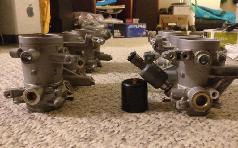
I also looked at the injector ports. Suffice it to say, they wont work as is.
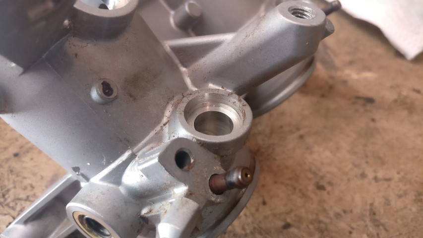
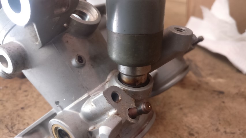
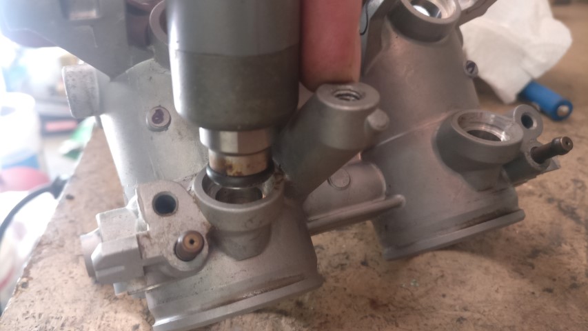
As the last picture shows, there’s a bit of interference with the fat injectors and the fuel rail mounting post. I’ll likely have the skinny-style injectors for this intake by the time it’s ready to go on, so I’m not sure that’s relevant. I’ll need to make some type of adapter bung to get the injectors to fit properly. Wish I had a mill. Looks like I could just bore the injector ports a bit larger to fit the Bosch automotive units if I could clamp it to a solid table from which to indicate. Would injector spacing from the runner itself have any meaningful effect on the spray pattern? I would have to imagine it does, and I would want the injector to spray as closely to the runner as possible, right?
I want these to be DBW. I don’t know why. I just do.
Thinking about anodizing the throttle bodies themselves red and putting gold velocity stacks on them. Everything else black. Thoughts?
This is exciting.
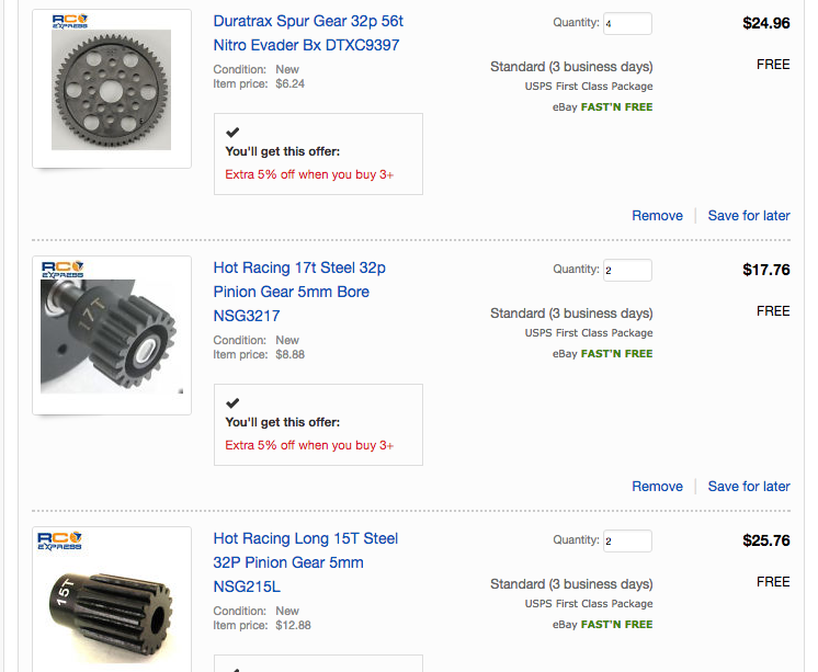
Couldn’t wait. Ordered a gear train. Steel pinions, plastic spurs. If they’re good enough for 1/8 scale R/C buggies, they’re good enough for throttle body actuation. Overall 12.29:1 reduction, giving me ~6.6Nm holding torque from each ‘servo unit’. One servo per bank, with a sturdy return spring, mainly for safety. The TPS voltage dropping when I take my foot off of the throttle should be enough for the steppers to return back to closed, but that’s not a chance I’d be betting on.
So I’ve got my throttle bodies, stepper motors, h-bridges, gear train, Arduino, test TPS and everything else I need to get something together. I’ll need to make two hubs on which to combine a 56T/15T idler setup for each side, and two 10mm shafts with integral hubs for 56T spur gears to go in between the separate pairs of TBs and join the butterfly shafts. I’ll work on drawing that stuff up in the next couple days and maybe making some of it.
This is sickk!!!
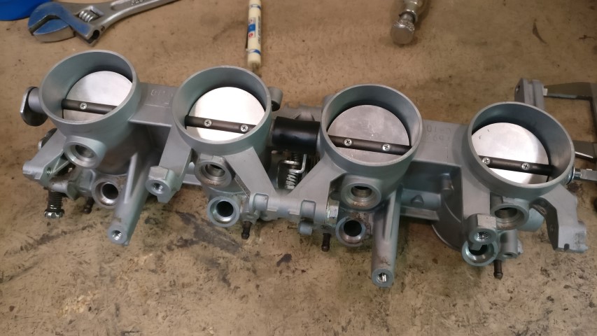
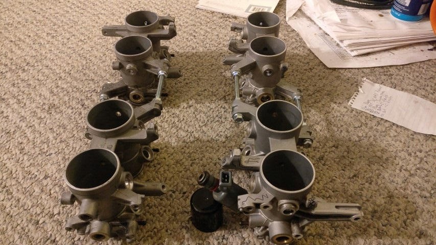
Got the other set of throttle bodies today and promptly stripped them all the way down.
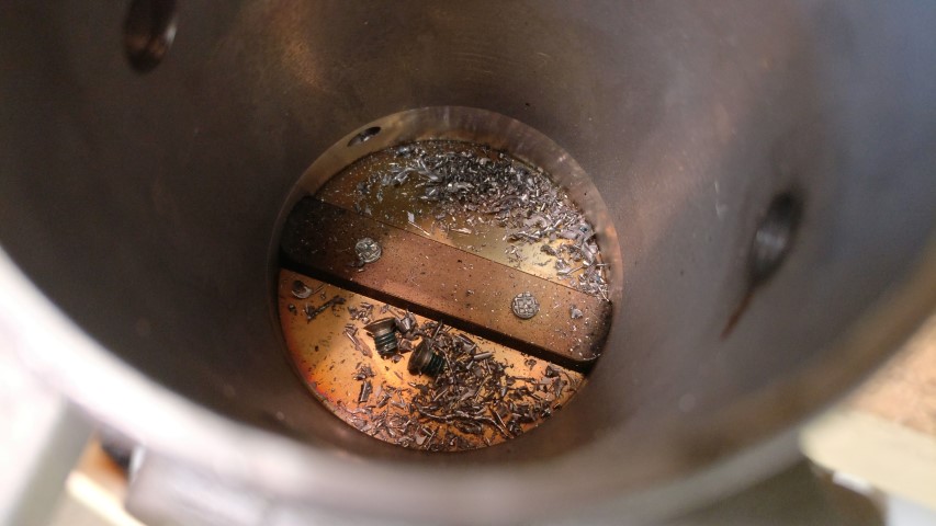
Drilled out the secondary blade butterfly screws and removed all of that garbage. You can also see how Mikuni swage the tip of the primary butterfly screw in addition to LocTite. I wouldn’t worry about these finding their way into the motor. Until I removed them and fucked it up. Hah.
So then I got my temporary threaded rod in there to space the units apart 2.25" and couldn’t resist setting them next to each other at a bore spacing that I thought would look somewhat reasonable.
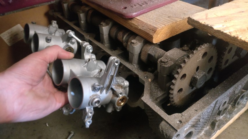
And then I had to drop them onto an upside-down intake manifold to give me an idea.
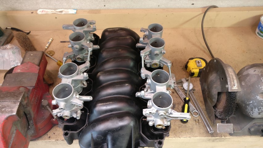
Yeesh. That looks awful. Not symmetrical, super wide bore spacing [9-5/8"] - just looks bad. It doesn’t help that I haven’t shaved the now unnecessary aluminum bits off of the TBs yet, but I can at least look past that. Instead of using 2" velocity stacks on the outside opening of the TB, I can just add that 2" to the TB - intake port runner, giving me 6" for those. This will precipitate the use of either zero length trumpets or nothing at all on the openings of the TBs. Also, although the intake flanges on the heads are horizontal, the port through the head to the valve pocket is, of course, not vertical, so it would be foolish to simply drop the vertical TBs directly onto the flange without some type of compensation. Instead, I’ll align the TBs for symmetry and move each bank a bit closer together; something like ~7-7.5" bore spacing. This will require some gradual sweeping runners bent at something like 18"-24" CLR. Not too sure yet. I want to get the throttle actuators setup and the TB banks themselves joined before I make an intake manifold for it. I plan on using those threaded rod bosses as anchor points for a ladder frame to hold all four TB ‘units’ together before attaching the runners.
Another inherent benefit is the ability to run a new common fuel rail for all eight injectors. I discovered that the injectors appear to be located at a 45° angle to the vertical TB. Interesting. I’ll measure to verify, but this means that I should be able to use two adjacent sides of a piece of 1" square tubing and eight more injector bungs to make the singular required rail.
You can kind of see what I’m on about here:
I’m going to work on a jig with which to make that ladder ‘frame’ for the TBs this weekend. I’d like to get them all assembled into one unit first before worrying about placing the fuel rail, both vacuum collection circuits and finally, both servo drives and controller module. Good thing there’s plenty of room in there.
I don’t really like this set up.
Make a flange with some angled short runners that align the TB nicely. A single square fuel rail would be super nice if you can get away with it.
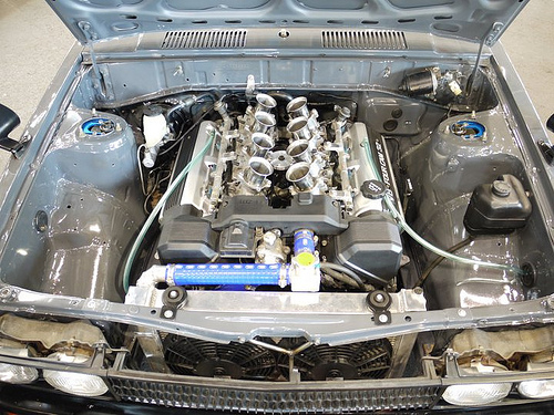
Wanna know the best part? Those are carburetors. Dellortos, to be exact. Guy that build that car was a a bit strange.
Not sold on the rail. I could do a round rail and then I’m not married to a 90° separation angle for the two banks of throttles. Still need to package two vacuum cylinders in there and still have room for ~16 vacuum lines and fittings.
This forum doesn’t let me edit. Maybe I’m dumb.
Anyway, my main goal is direct, straight-as-possible uninterrupted air flow from TB opening to valve. Think mini [short] tunnel ram with independent runners and a throttle body at the top of each. I hope it’ll look okay. Maybe I can CAD it and see. I should have enough relevant measurements.
Fucking shit can the ITB and work on the Triumph you cheuch
Hah! You make a valid argument.
agree witchya
took the words right out of my mouth
Hearing it run makes me more upset I didn’t snag that one with the blown motor.
Do you have the little deflector that snaps in when you have the sunroof out? If you do you should stay dry in the rain as long as you’re going at least 30mph. They go missing all the time but I found one on ebay back when I had mine.
So this is exclusively a motorcycle forum now? Hah. Let me at least move and get situated in the new shop. I’m playing with the ITBs now because I just got the car working and I have some pretty hefty ADD. The Triumph wasn’t likely going to be a thing this summer anyhow. Hopefully I’ll be back to work on that next month.
Yea, I was about an hour too late and a garage bay short for that one, but it was worth every penny of $600. Decent GT taillight lenses alone are worth that. Still haven’t closed on this fucking house, though. I’m getting aggravated.
I have the deflector. In the video, you can kind of see me fiddling to get it to sit in the slots for it up in the front compartment.
My main problem isn’t the rain itself as I don’t really mind it all that much. The main issue is that I don’t have any defrost and the windshield fogs up dangerously solid pretty quickly. I have a workable solution for it, just haven’t implemented it yet.
Guess I need to finish the Triumph first. Hah.
Finish the Fiero first because, well, I’ll let Clarkson explain why…
Also, the first 50 seconds of this explain it really well:
I’m in love with this, but this looks like it’s on an LS which doesn’t have heads that are even nearly as wide, so a crossram setup is feasible with short-ish runners. I love that throttle linkage. Looks like a Penny & Giles TPS, too.
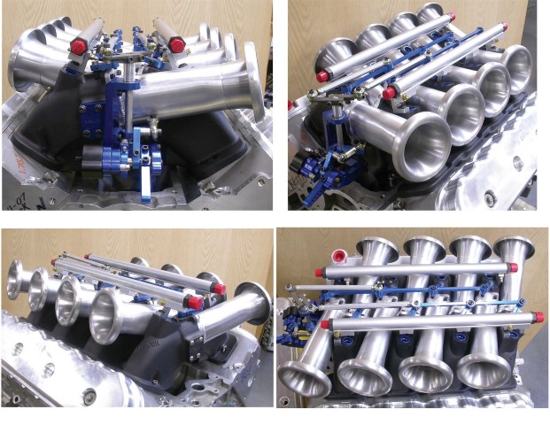
Instead, I think I’ll try to angle the runners inward to bring the bodies as close together as possible. If they’re close, I don’t even think they’d look bad offset for injector clearance. Something like this 1UZ setup.
I don’t believe that I could do a crossram with these TBs as they’re units of two, similar to the Dellortos. Maybe I should start looking for reasonably priced 40-42mm individual throttle bodies. Design my own? Hmm…
