there are a couple of them. The lovefab was one of the first then the one by whitesol. I was inspired by their projects but I felt like I could do the rear fabrication cleaner and with much less cutting and welding than they did. I my opinion, as much of the factory structure should be kept in tact as possible because it’s specifically engineered to perform. Often when people try to modify it in their garage they end up adding much more weight and structure (often in the wrong places) than whats needed because they don’t do any type of technical assessment of their designs.
---------- Post added at 09:27 AM ---------- Previous post was at 08:57 AM ----------
A quick history lesson; Honda had been rumored to have originally designed the sol as a MR drive car to compete with the likes of the fiero and MR2. Either this is simply not true or Honda decided against it for some reason but it’s likely the rumor started due to the size of the trunk and the shape of the rear window and sail panels. Despite most people being familiar with the car, no details of the build/design of it have been shared.
The next was the lovefab took a del sol and “tube framed” it with what looked like 2"x2" square tubing and had an H22 due to the cable linkage of the transmission.
The third that appeared was done by white sol on Honda-tech and this was has a ton of pictures of the build. He used a donor car to steal the front bulkheads from and welded them into the back.
I don’t like how this one went together all too much
The third was built by “tim” and some pictures of the build have been leaked but with no details. Its pretty obvious as to how he built it, but how he tied it all in to the unibody I am still unsure of. This swap used a k24/k20. This one is obviously the most rigid and most structurally sound, but I’m curious as to the cost in weight from that heavy rectangular tubing.
Focus, you’ll get it… Lol. And if not, here are the cliffs notes; this had been done before, but never up to my standard. Mine will be done better than all of these.
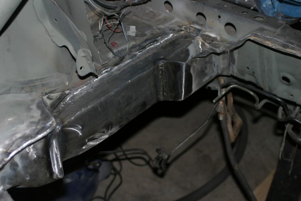
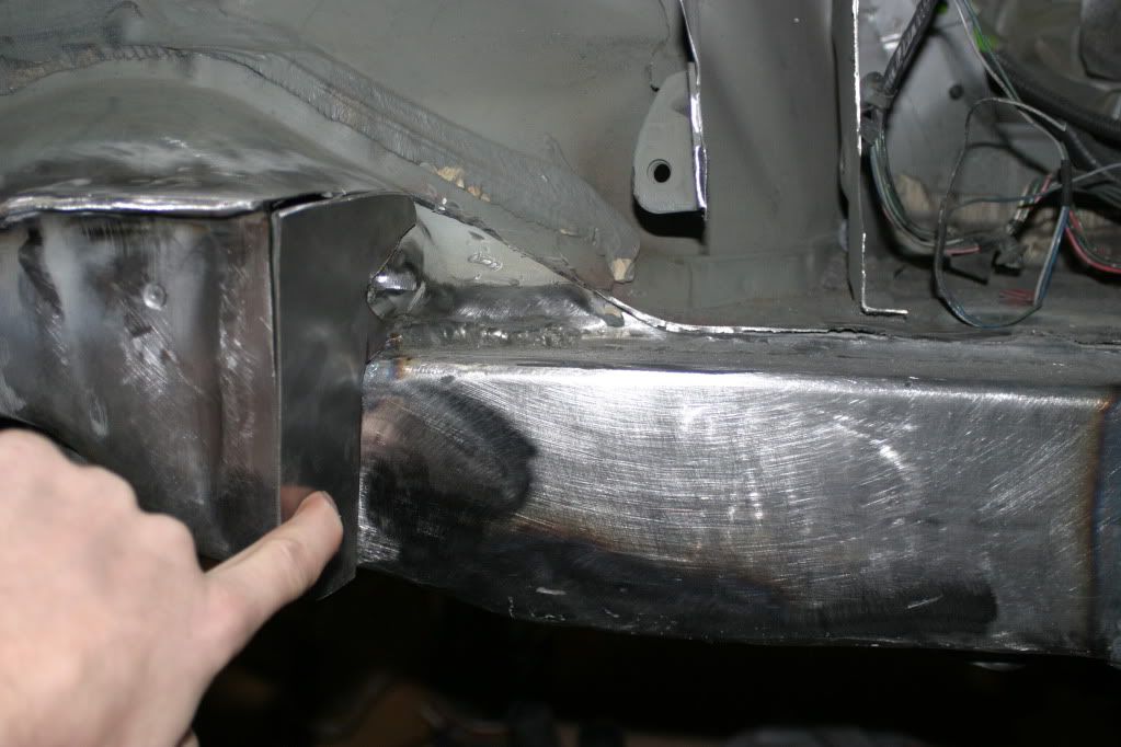
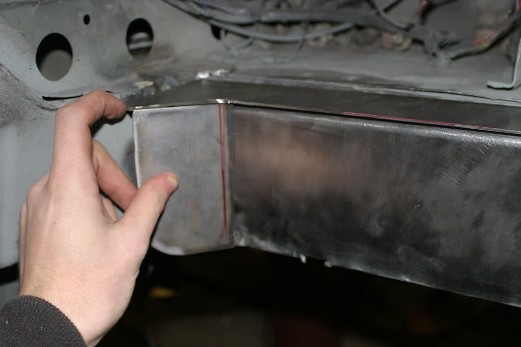
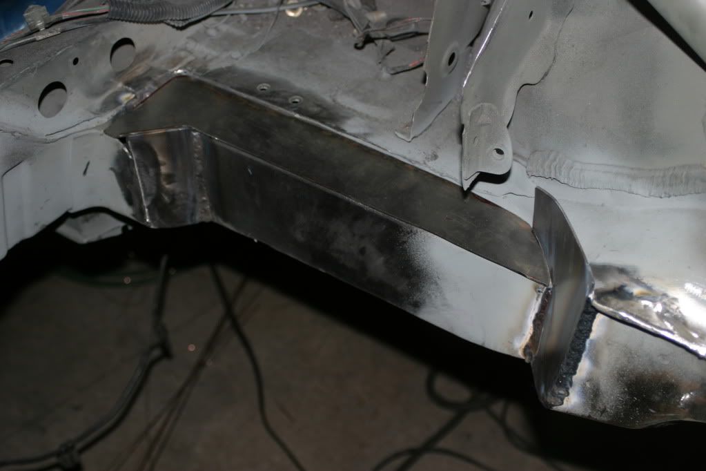
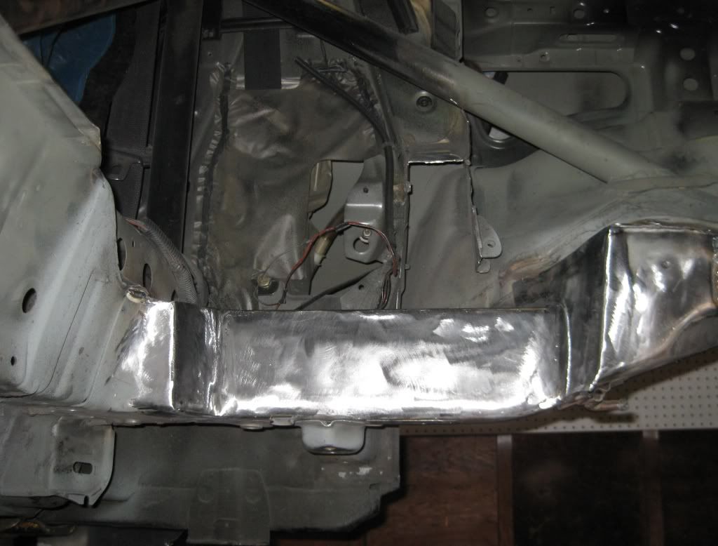
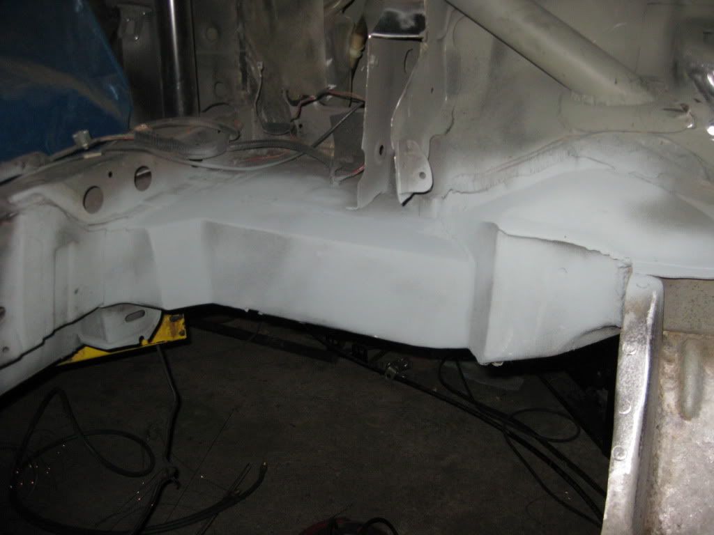
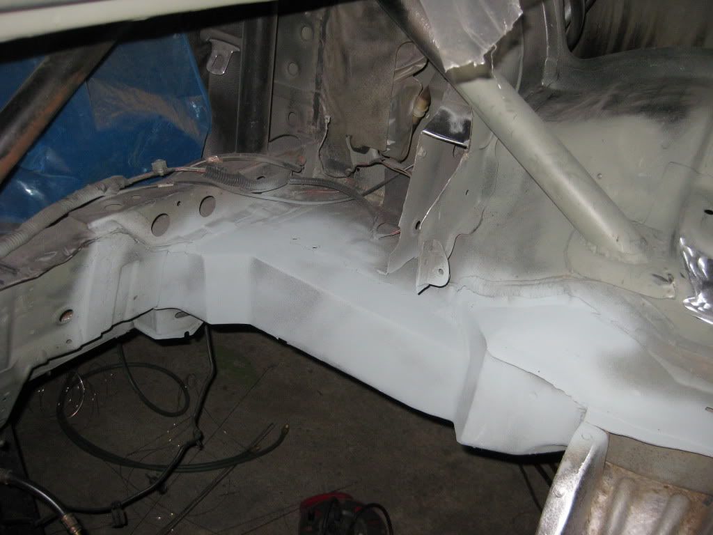
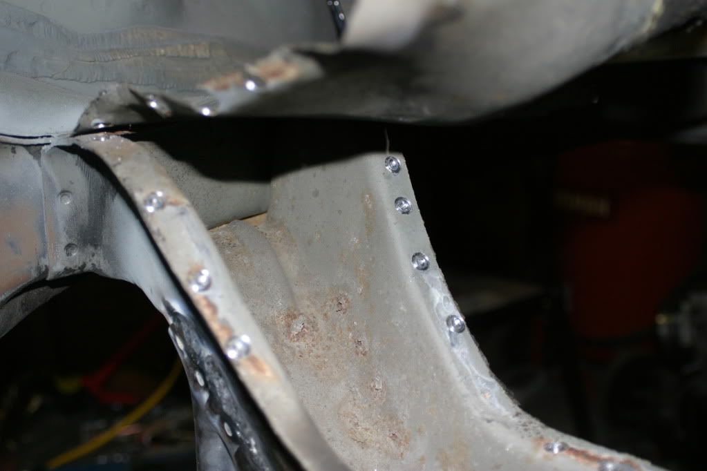
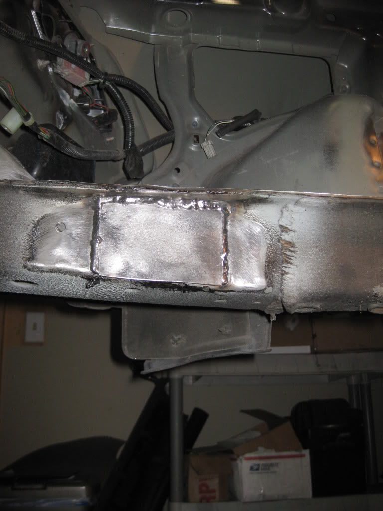
To assemble the frame rails and tie in all the structure I again made cardboard templates of how I wanted to cap off the frame rail ends and then a plate to go across the top. Unfortunately despite my metal prep I did end up with a bunch of issues with contamination requiring me to cut/grind out and reweld. For stubborn areas I used 309L which is meant to weld dissimilar metals but also has the ability to fill in spots with contamination.
Some of the contamination was from the factory metal but the majority of it was spots where I hit my weld through primer which forced me to discontinue it’s use.
Another small welding issue came with the 18g sheet metal skin across the top. When I tried to simply tack the thin skin to my 14g structure it blasted it to pieces.
The last batch of photos…whitesol? was the one I saw on HT a few years ago. I regret selling my rusty old sol everytime I see one around here. It was a trooper that’s for sure.
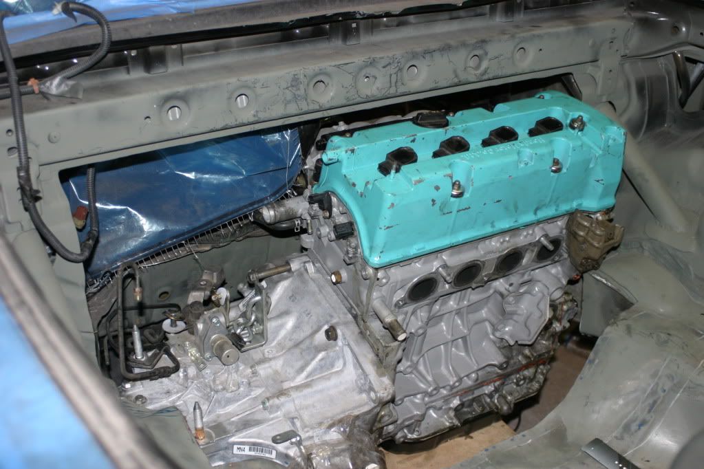
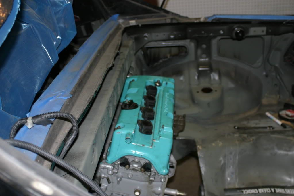
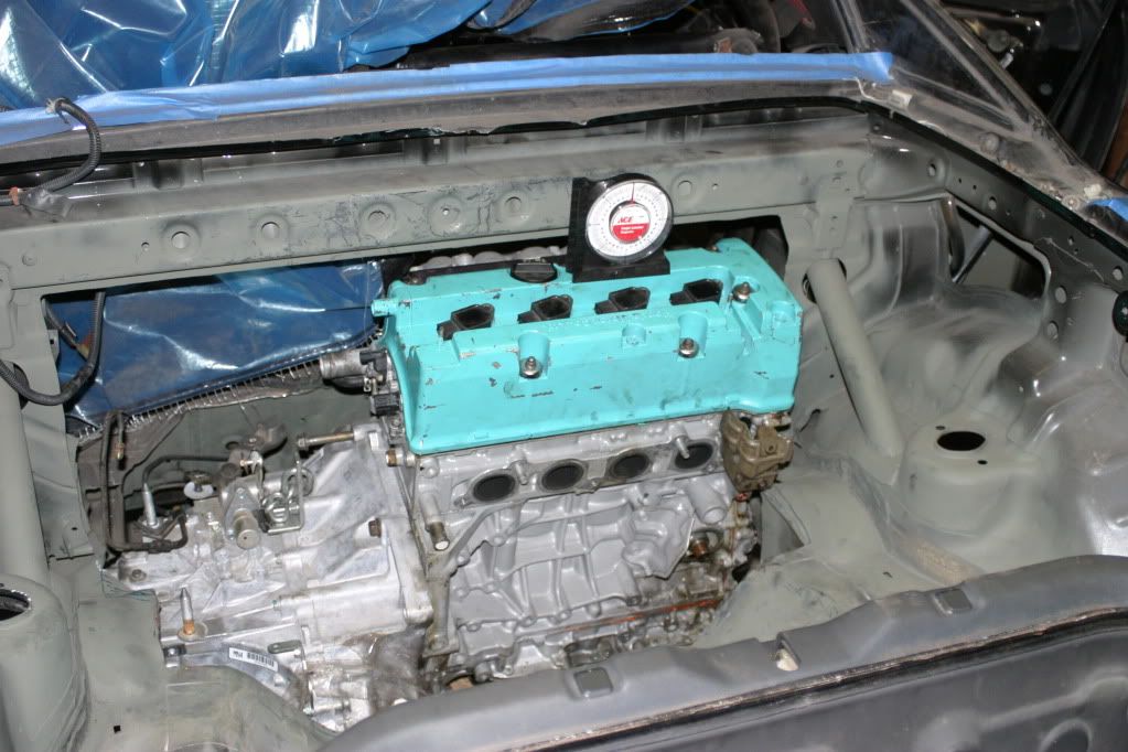
Here are the fun pictures. I’ll just dump a bunch of them in here and then go back and explain when and why I took each shot. some of these may be mixed up since I’ve taken so many shots of so many mock-ups throughout the process of the build.
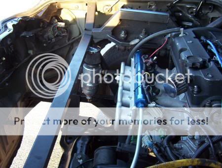
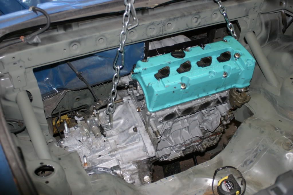
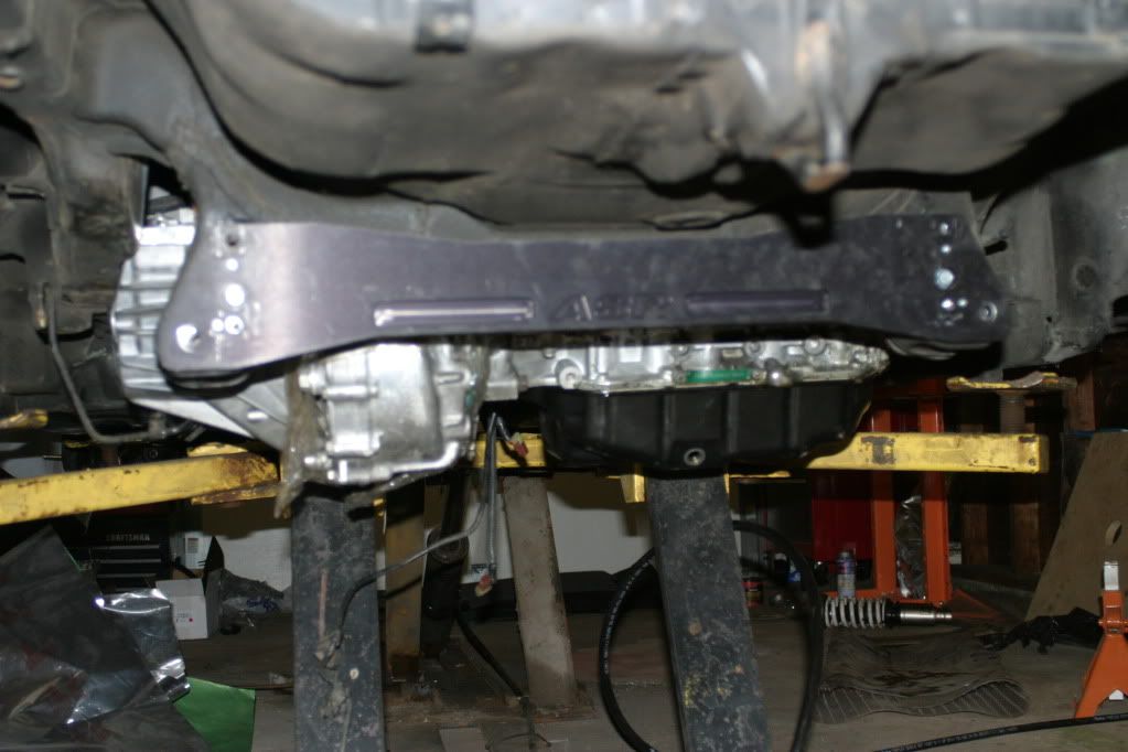
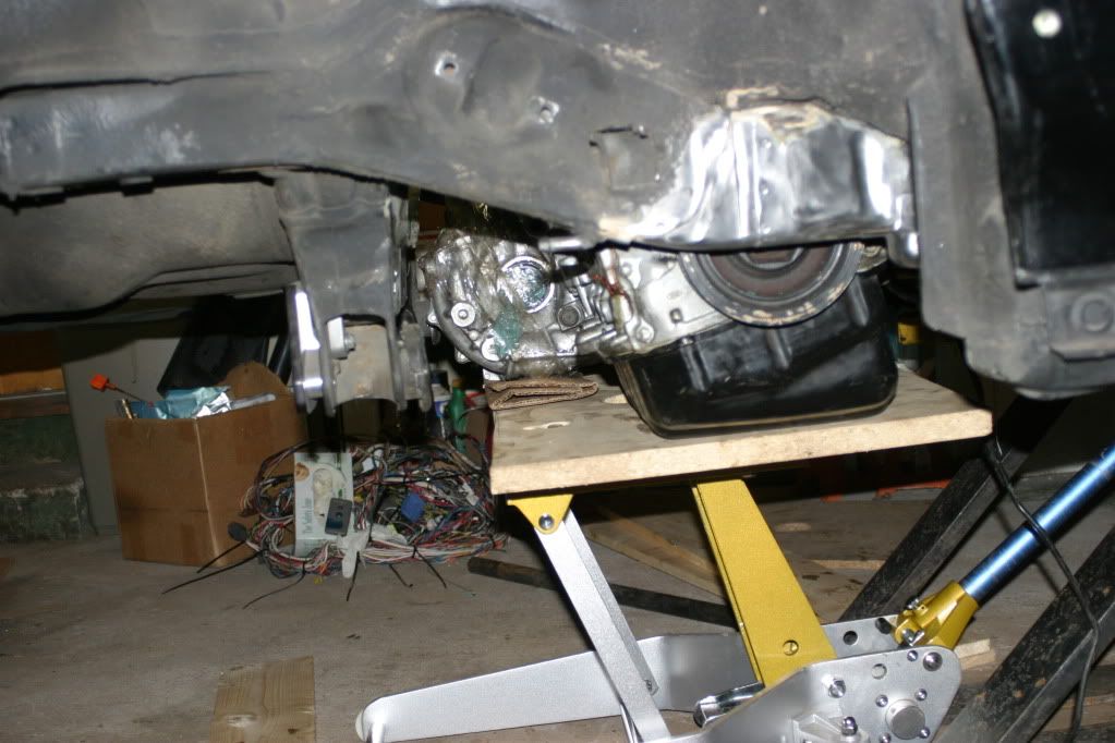
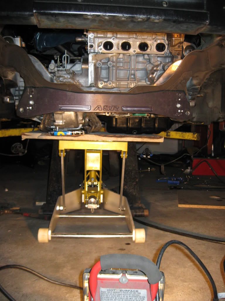
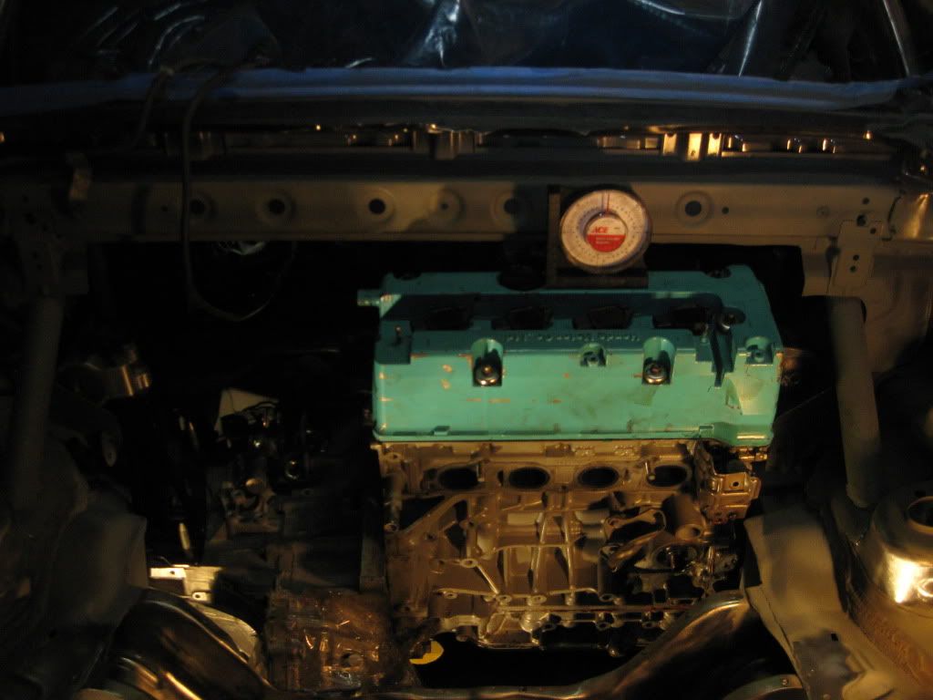
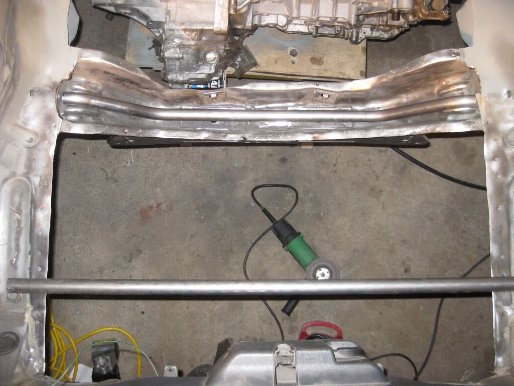
A close eye was kept on the ground clearance. Ideally the motor shouldn’t hang more than 3" below the subframe brace. For this mockup the frame rail with was not quite right yet and the motor couldn’t be lifted into place all the way.
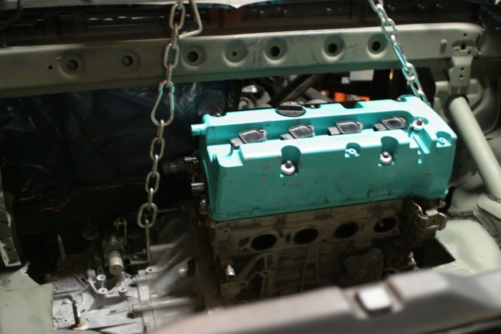
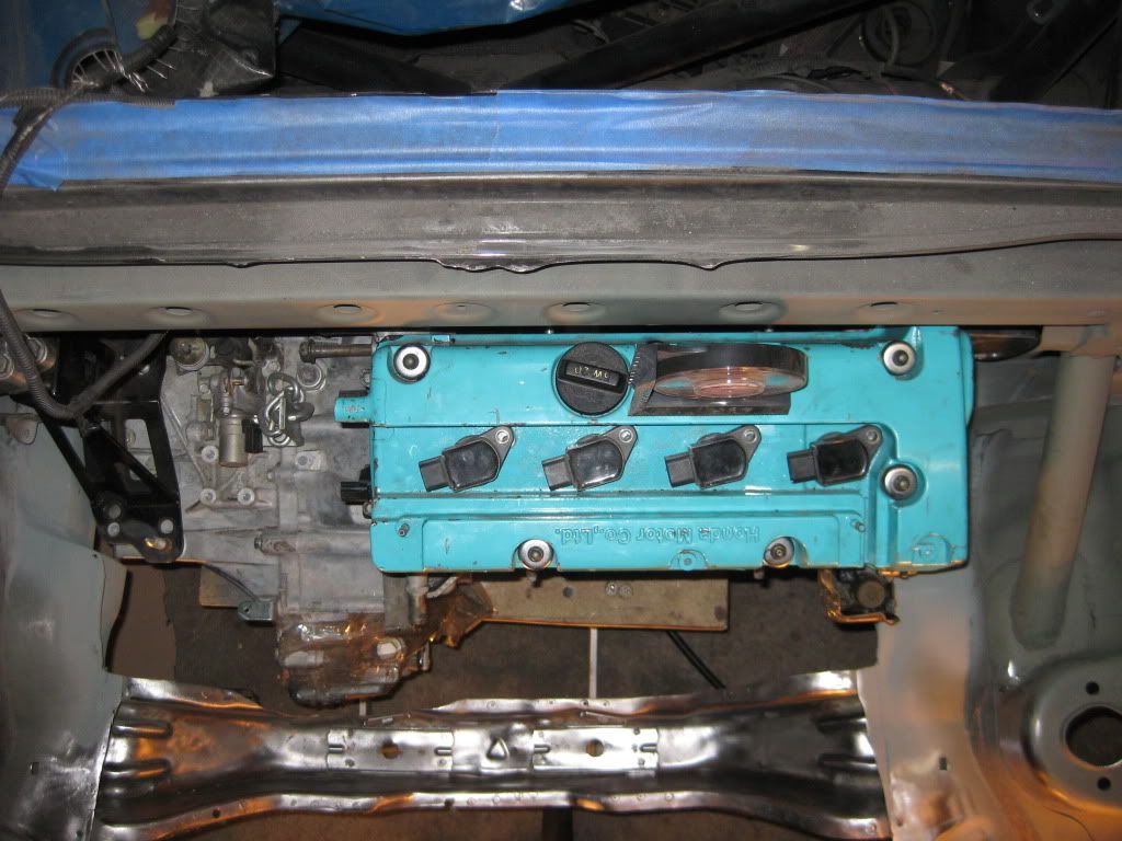
The hoist proved ineffective at lifting the engine into its location properly due to the chain centered over the motor contacting the rear firewall structure under the rear window. This forced me to get creative with my method of getting it into place. the “engine bay” lends itself to installation from the bottom and that is how I sketched it all out to work. My access from the bottom was limited by the fact that the valve cover of the motor barely cleared the subframe when the motor was on the ground and the car/lift was all the way up. This meant that in order to get the motor into location under the car the lifting mechanism would have to be very low profile.
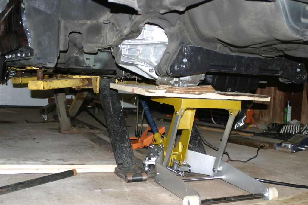
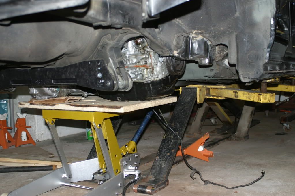
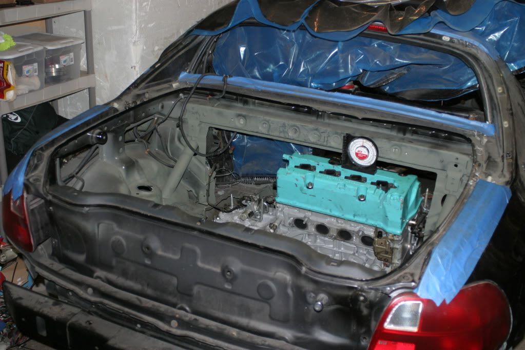
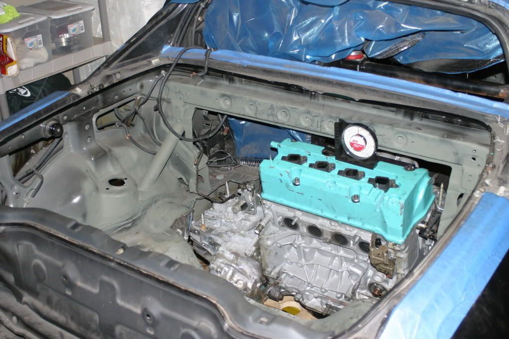
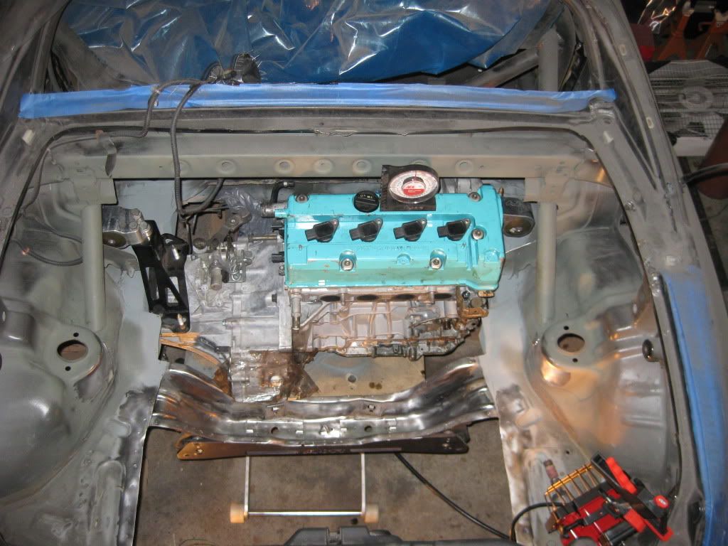
The solution, at least temporarily was a motorcycle jack with a wood platform bolted on for now to support the engine.
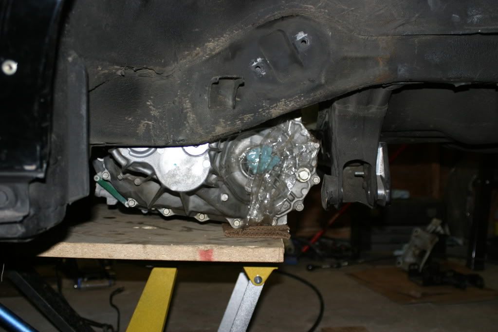
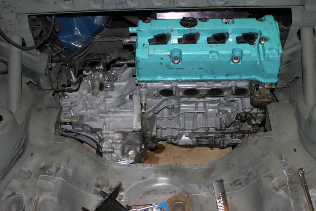
the platform allowed me to center, level, and raise the motor into the correct position easier. In the next two shots you can get a good idea of how the axles will line up. The subframe is about 1.5" behind the axle line of the car so the axle angle should be low enough to avoid problems.
If anyone cares for the details I’m going back through and adding some more technical descriptions to the pictures I’ve already posted. If anyone has any questions about anything post up. I hate it when I feel like i’m talking to myself on here.
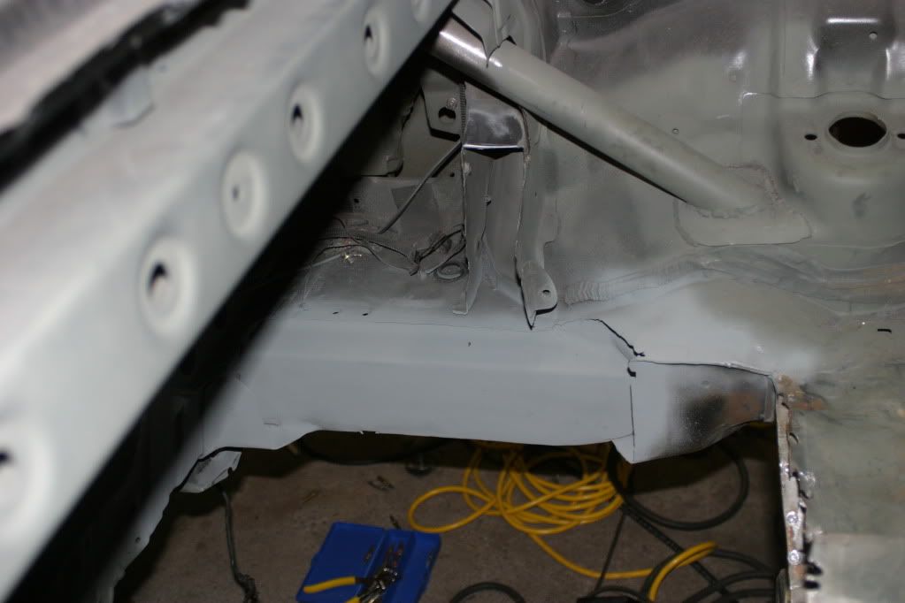
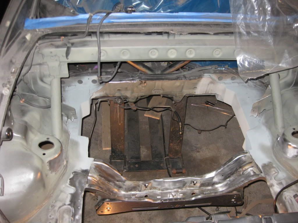
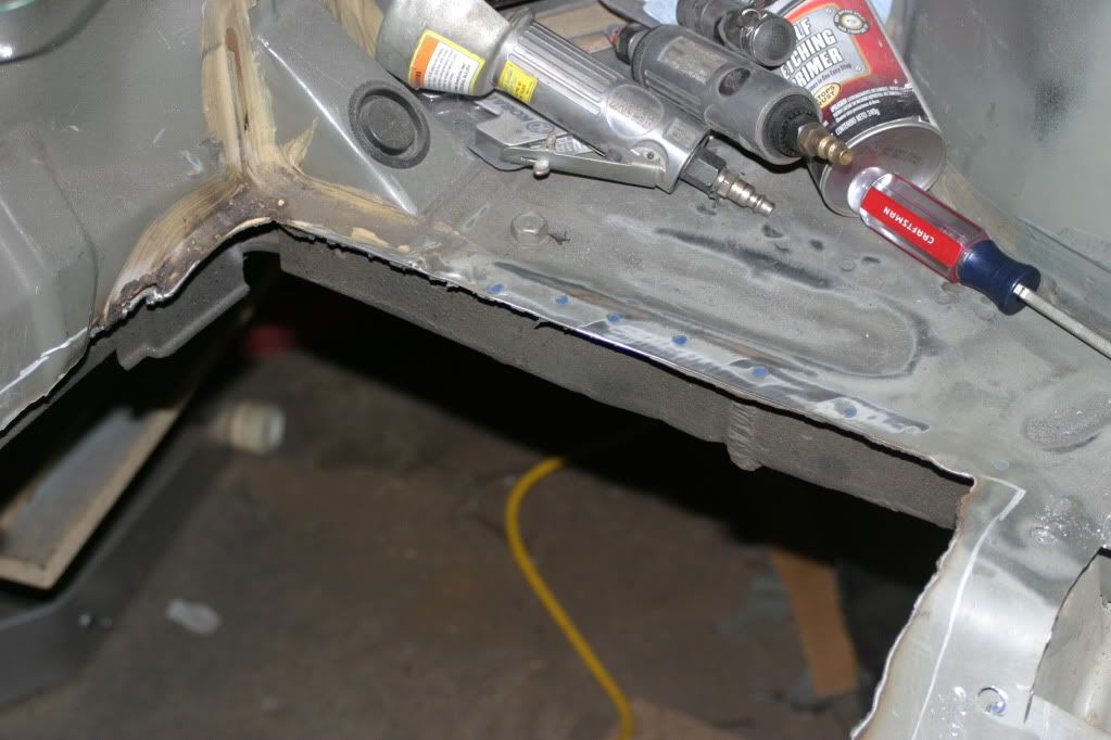
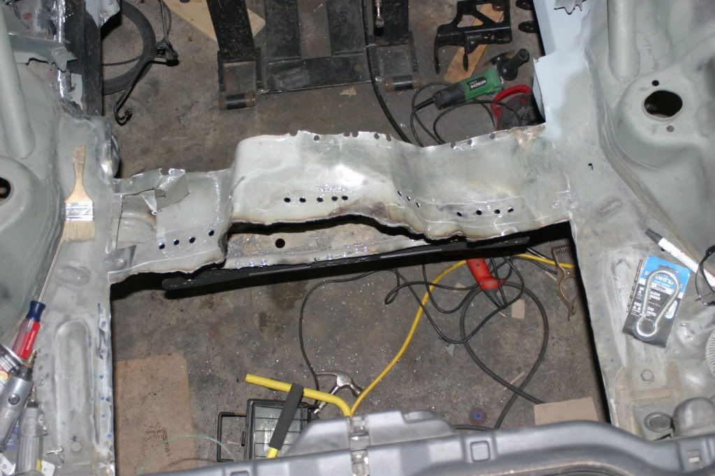
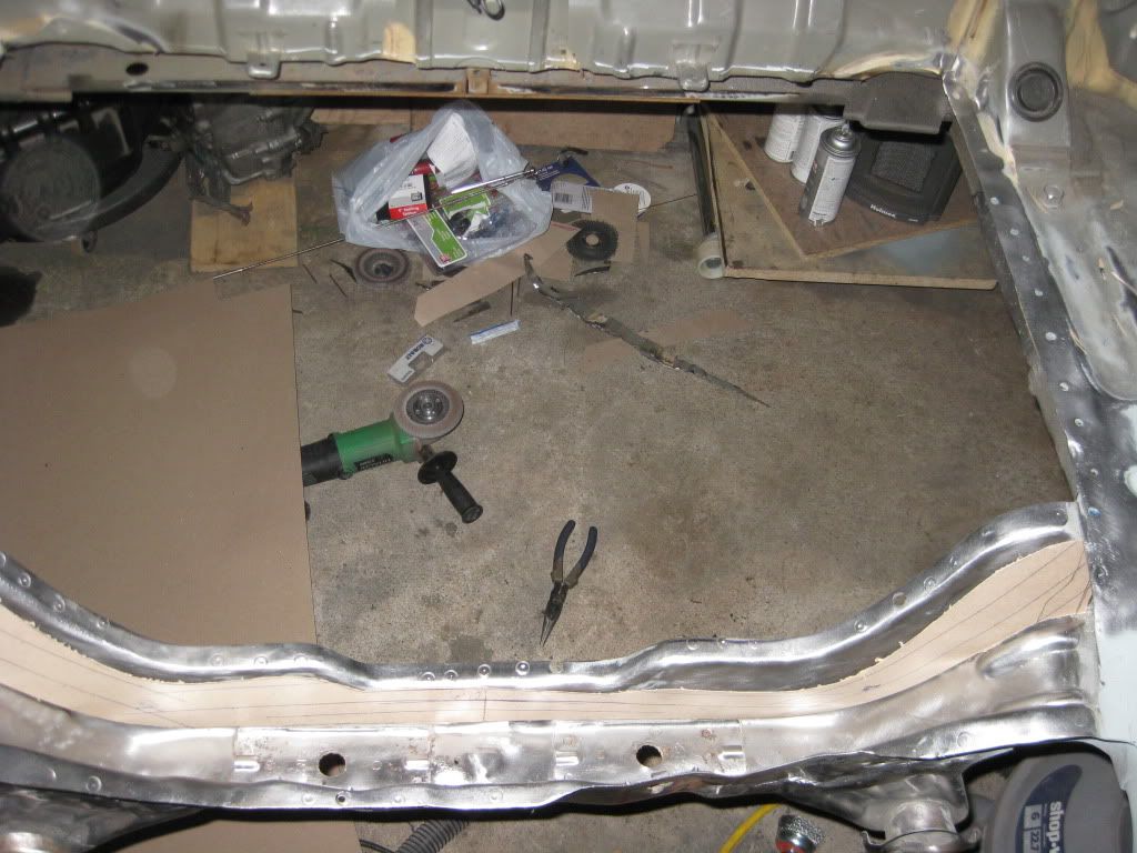
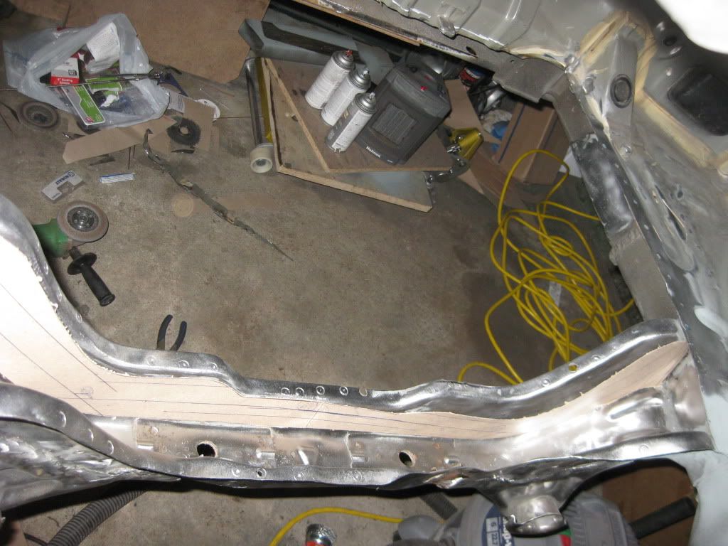
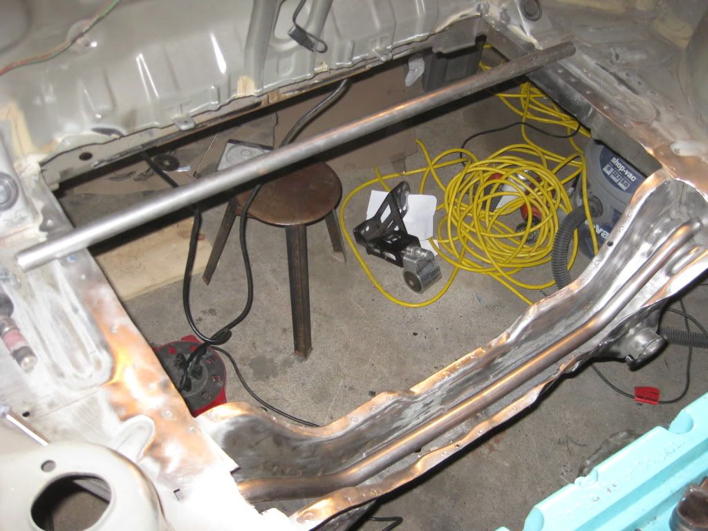
Somewhere in the middle of the mockup process posted in the last three posts I did some more work to the spare tire well and subframe.
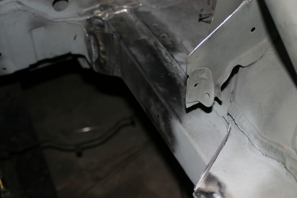
First task was to remove the spare tire well without cutting into the frame rails or other structure. Cuts were marked with a paint pen, then cut 1/2" to the interior with the plasma cutter. A grinder with a thick cutoff wheel was then used to clean it all up and slowly inch it closer to the cut lines.
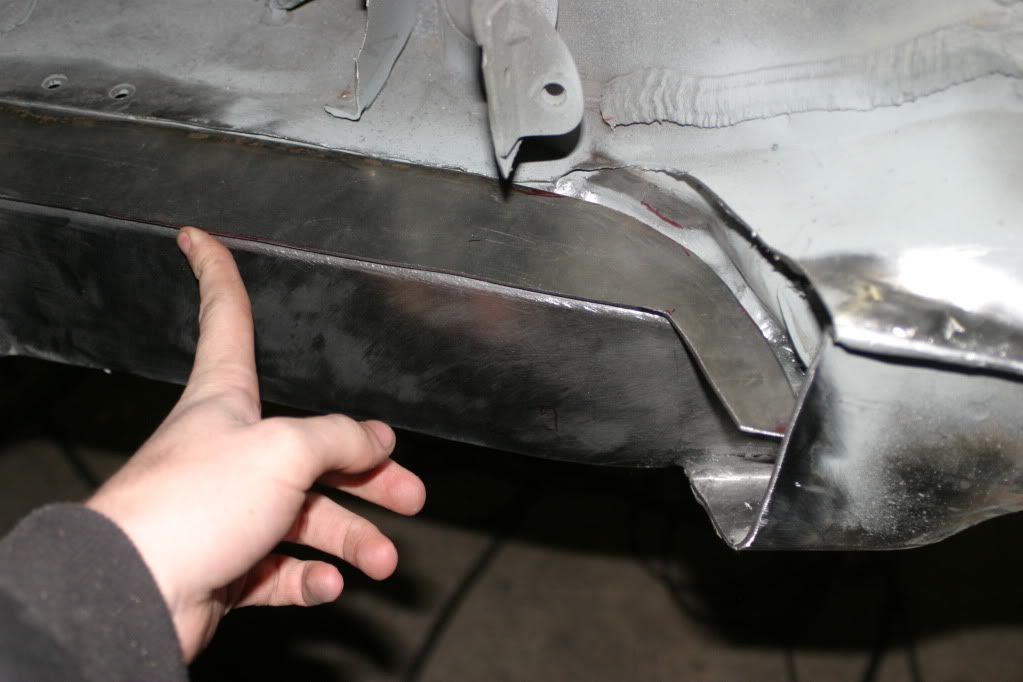
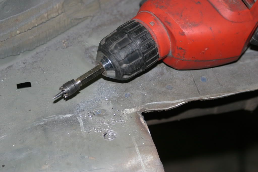
For the skin over the subframe I luckily was able to find a spot weld bit that I didn’t have to pay $10 shipping for, just $5 at harbor freight and I was able to trim the ends and pull the metal right out.
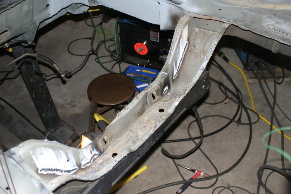
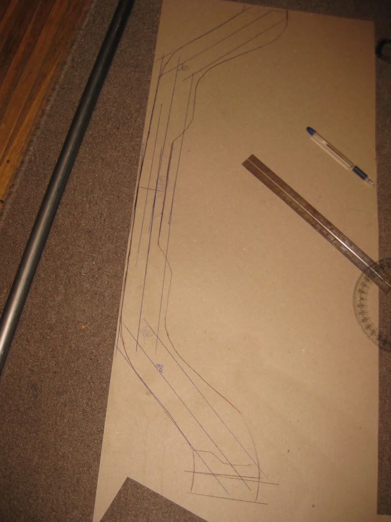
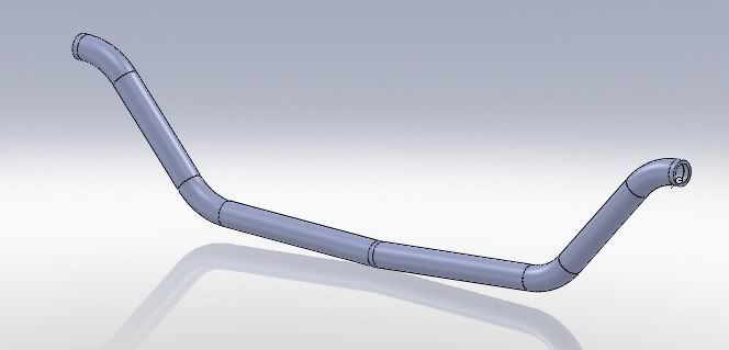
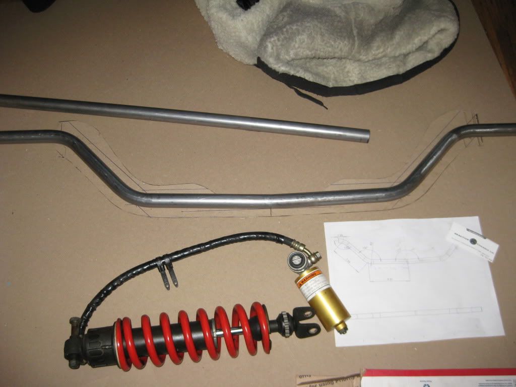
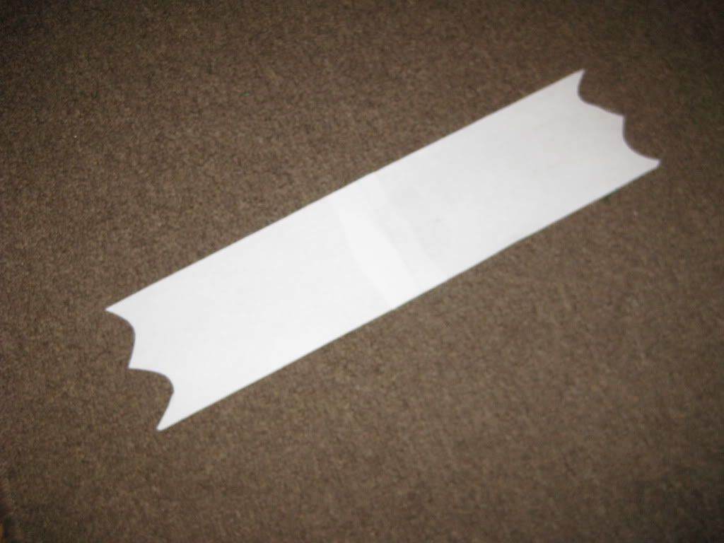
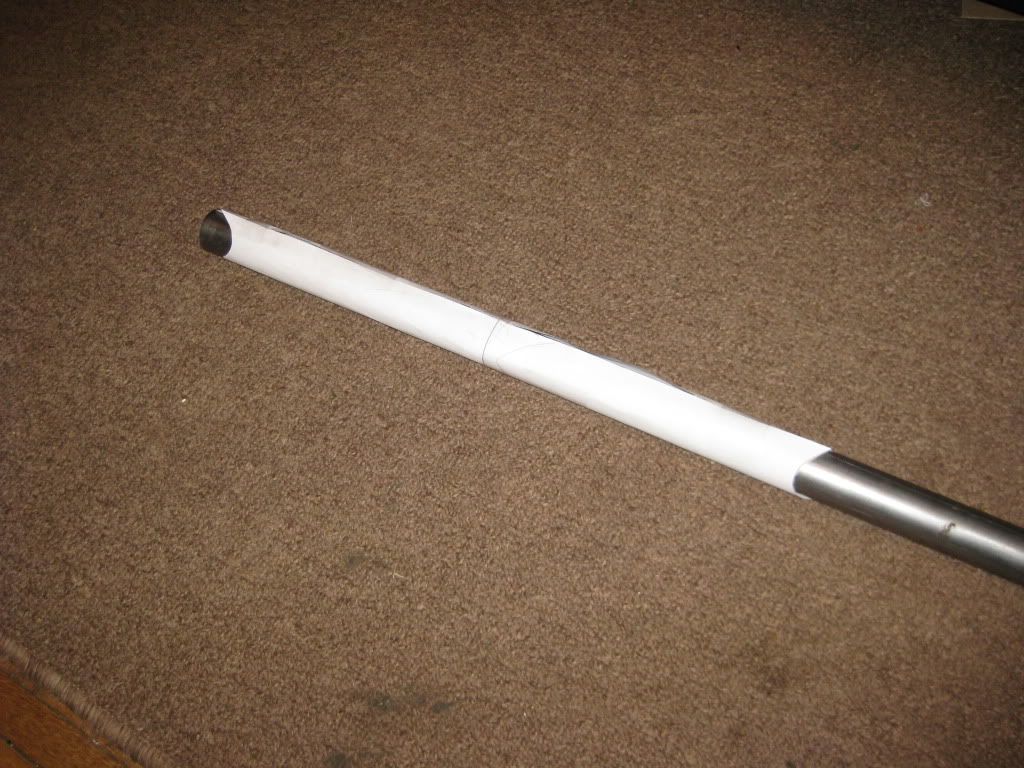
from the angles drawn on the cardboard template I punched this in:
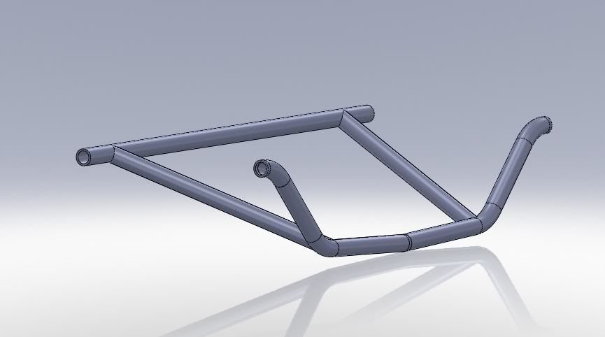
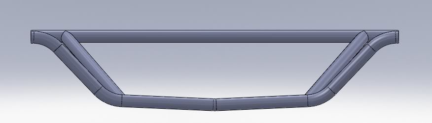
Drew up the model for the part. My original sketches for reinforcing the subframe were really misguided and I’m very happy that I kept working on it until I properly distributed the forces I was expecting through the structure.
i wish i had questions to ask you. i think honestly, from this point on, your not going to get any posts more constructive than “holy shit dude!!!”
“this is fucking wild dude”
“omfg i am rock hard, and oh wait… i just came”
this is a serious hard on for anyone that loves the noise and power of a k20, the look of a del sol, mid engine RWD burnout awesomeness, and the mating of all of the above in a fucking hardcore mouth fuck party
lol, plenty. I’m trying to do a real solid job of explaining the photos as much as possible particularly since I have hundreds of photos in dozens of folders to sort there and then figure out whats what.
---------- Post added at 11:15 AM ---------- Previous post was at 10:57 AM ----------
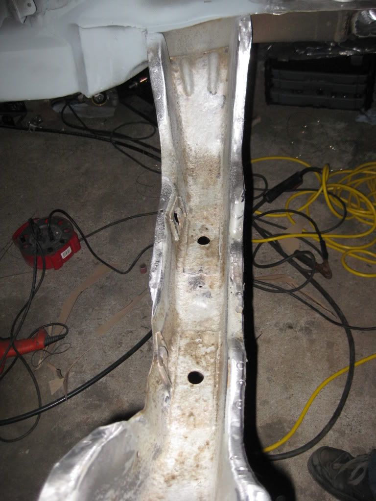
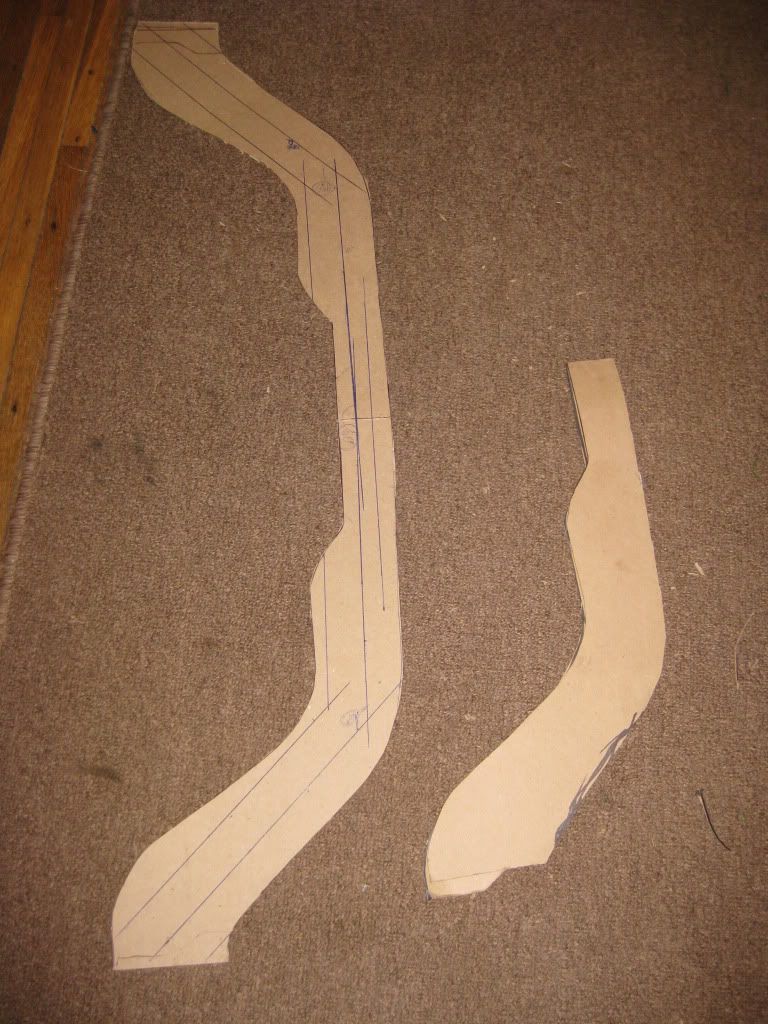
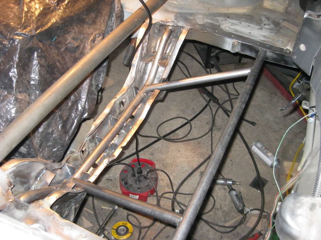
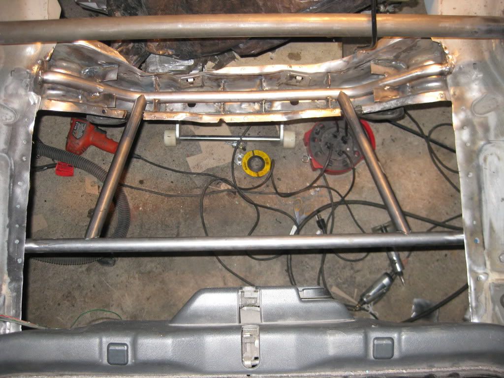
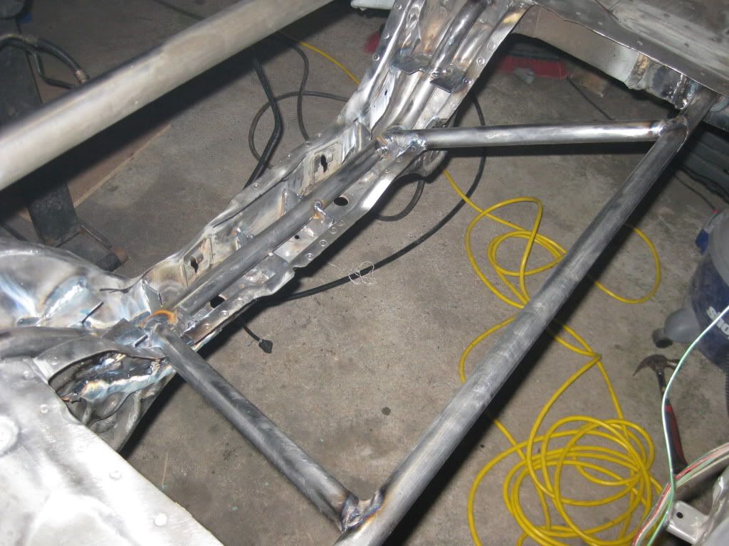
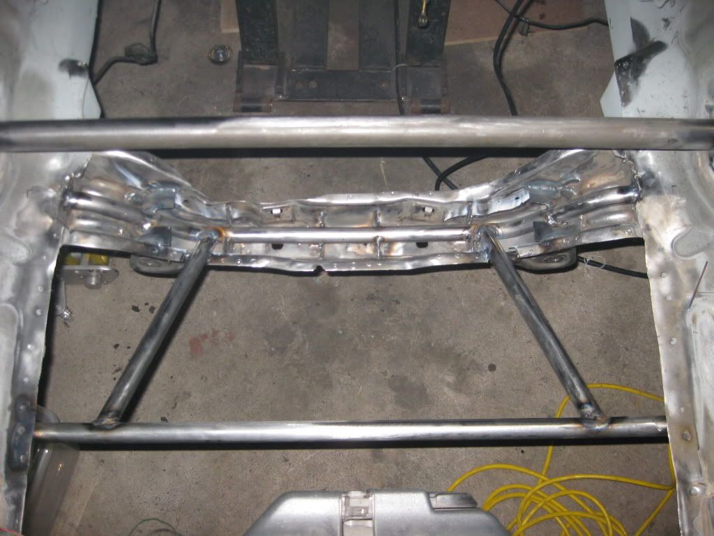
next job was to make cardboard templates and then cutout the gussets to tie the bar into the subframe. These photos are of the mockup. It was tough to get a tight fit on each of them and in the end I had a real tight fit of the two outside gussets, an alright fit on the next set, and then the inside two fit quite loose. I wasn’t happy with them but I went ahead with it anyway. This is something I’m going to have to revisit those later to make some adjustments to get them up to my spec.
any where that tubing is welded to the body plates are welded up first. I’m not the best welder but since this is my big project I wanted the first shot at it all. I’ve also had some help from a number of people who have came in and gone over my welds again in areas where they may look questionable.