that was the first thing that popped in my head. I’m looking into it.
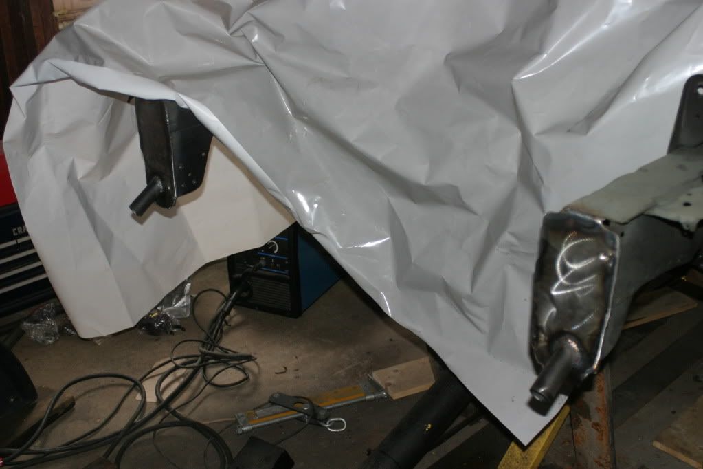
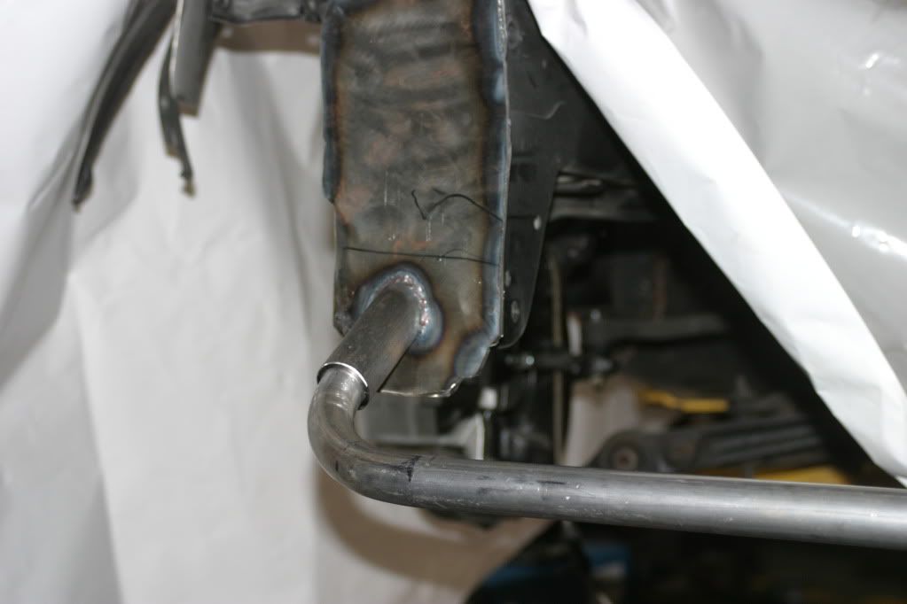
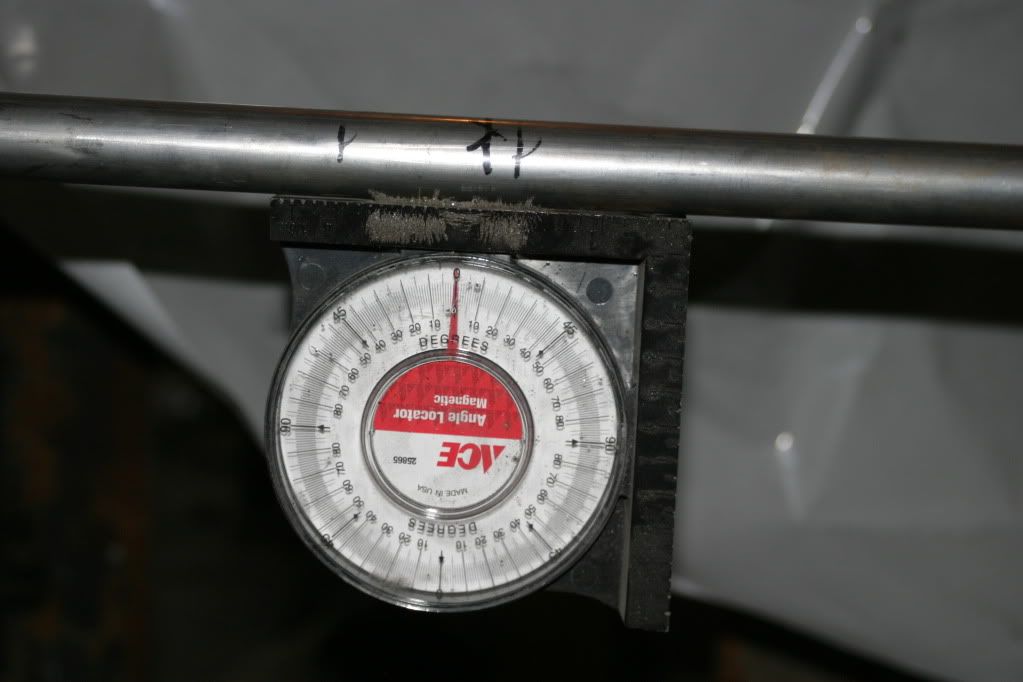
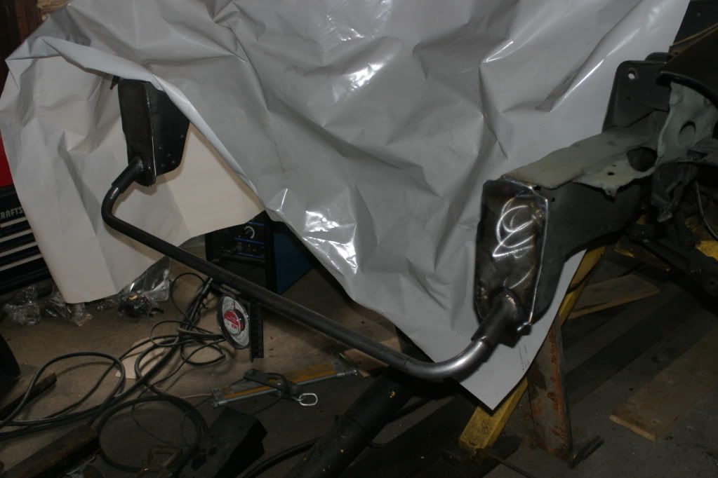
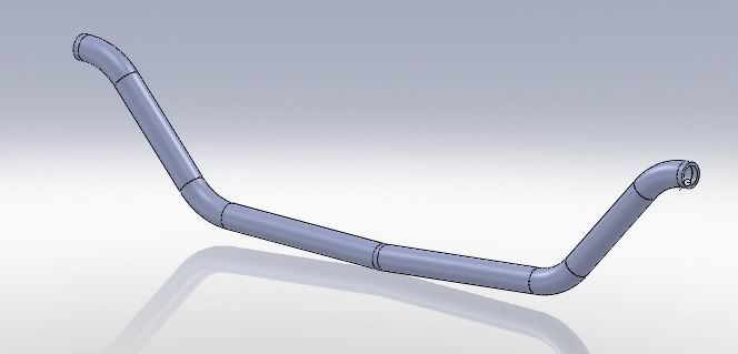
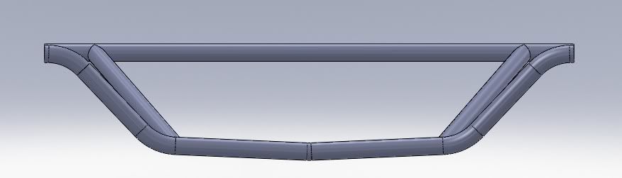
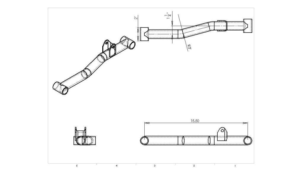
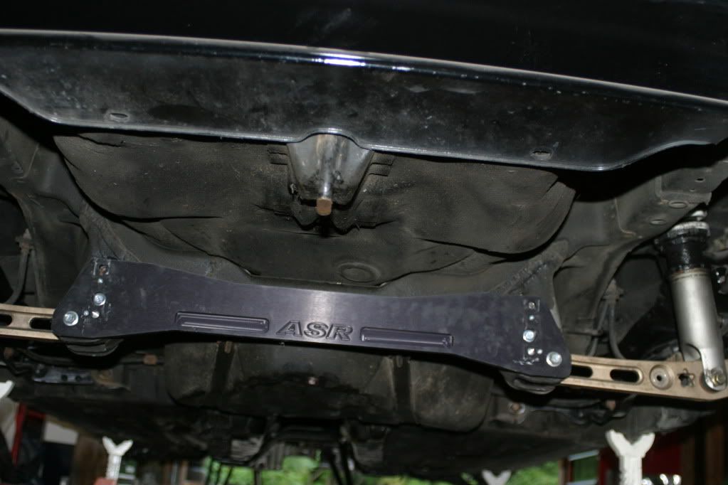
Finally installed my new front support. Ended up going with a smaller diameter tubing because it was easier to find someone to bend it to the tight radius I needed and I figured the larger tubing was a bit unnecessary.
On another note, the project is going to be delayed a bit as I have to move to Georgia for 8 months or so and then will be out of the country for a year. When I get back I’ll have to re-evaluate my goals for the car. 
lookin good
i like everything about this car except for the front lip add on. dosent match the rest of the body at all.
I disagree. But regardless, the lip is required for the splitter/undertray to be functional.
ok, two things to wrap up this thread. 1. I’ll be away from the car for the next two years on what we’ll call ‘government business’ 2. A lot of progress has been made and my plans have steadily been moving forward. I have decided not to post here and leave everyone hanging.
K series rear wheel drive del sol. Yes.
edit
alright, time for me to spill on this project. I’ve been planning, sketching, and researching the most realistic and cost effective way to complete this project. I actually come to a realization regarding the trailing arms that became the key to finally undertaking it.
Just to get started I’ll show the ground work of it:
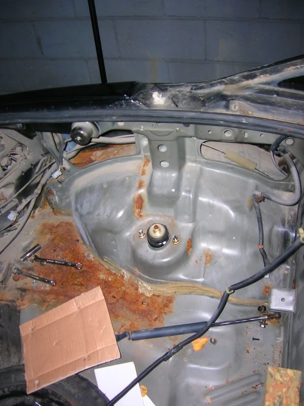
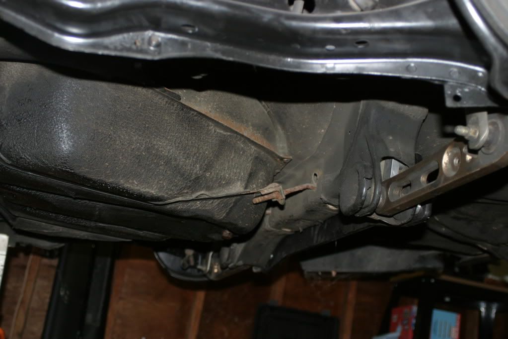
initial concept for subframe reinforcement. This concept was later abandoned because it would not actually prevent the subframe from twisting in the way that I expect it to. Subframe “tear out” is somewhat common on honda race cars running very thick sway bars and occurs when the subframe which is spot welded onto the spare tire well floor actually pulls off of the car.
Since I am removing most of the trunk sheet metal along with the spare tire well, I will need to beef up the entire component and build in something to resist the twisting forces caused by the sway bar.

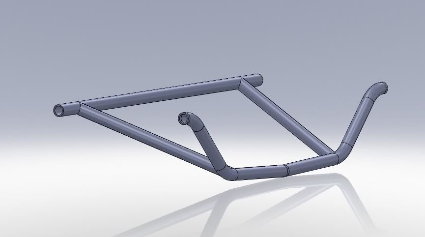
subframe reinforcement concept #2
the rest of the subframe reinforcement assembly concept in 3d model form:
LCA design. Offset ends required 1. to allow clearance for axle, and 2. due to the new trailing arm geometry. I am debating about either machining billet parts like what I’ve sketched below or having less expensive tubular pieces made. I like the idea of the billet pieces because at a glance they would look like typical aftermarket parts.

model of the idea:
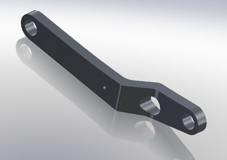
another concept of it:
rear floor concept. Replacement for spare tire well

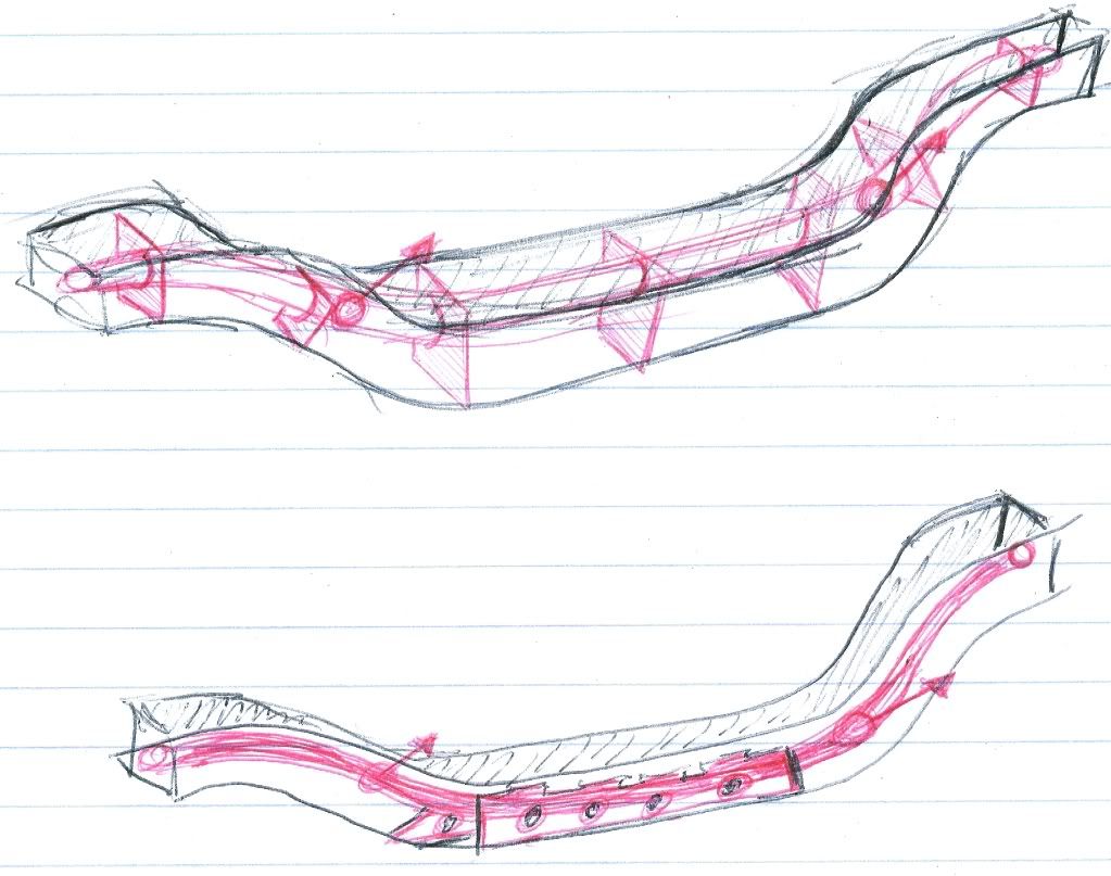
frame rail modification concept. because I have to cut the frame rails to widen them I want to insert a piece of structure tie everything together and keep it stiff and strong. The frame rails are a somewhat funny shape especially when taking into account the thin 18 gauge skin across the top of them. This sketch helped me figure out exactly what I wanted to do and what the insert would look like.

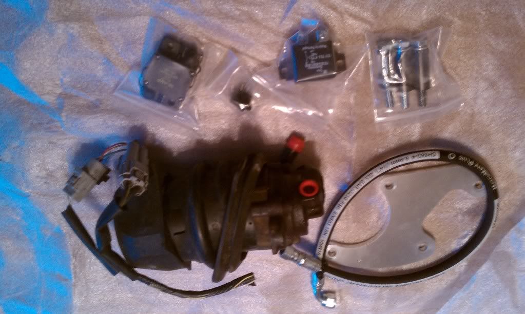
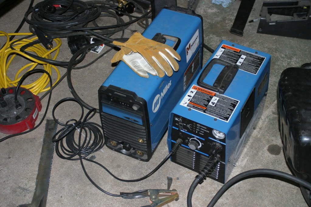
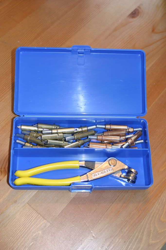
picked up some loaner equipment
some new tools
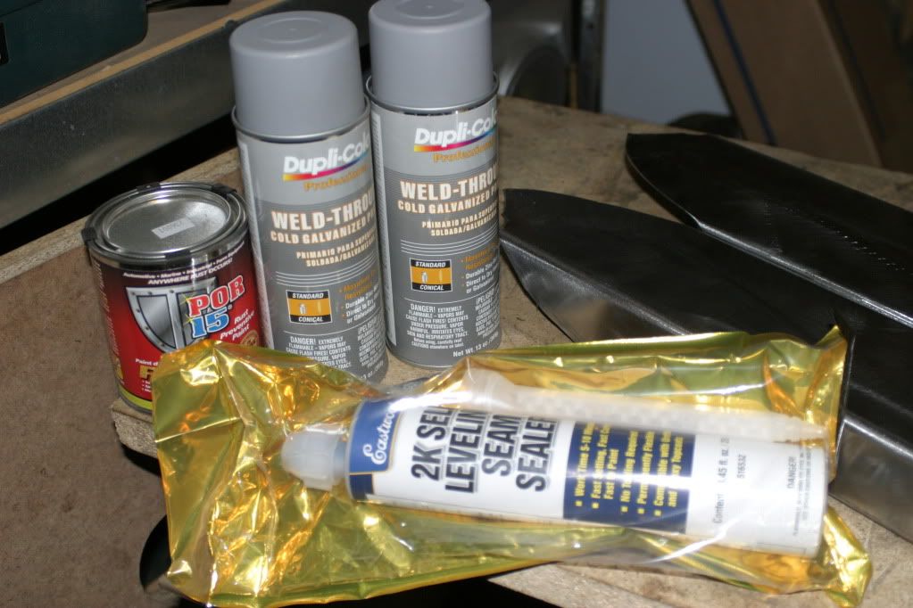
some materials
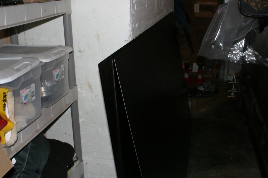
a parts car I bought a few years back served as part of my research
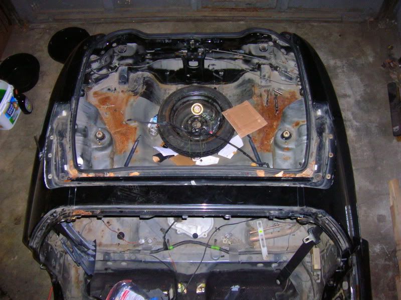
some reference photos:
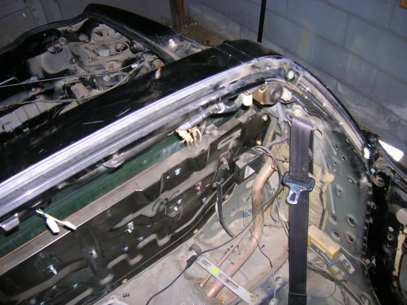
finally time to start cutting


cuts were rough cuts deliberately done 1-2" to the interior of where I need them to be. This allows me to trim with neater tools to get me closer to the edge.
This would be cool converted to rear/mid engine and RWD…
It’ll be interesting that’s for sure
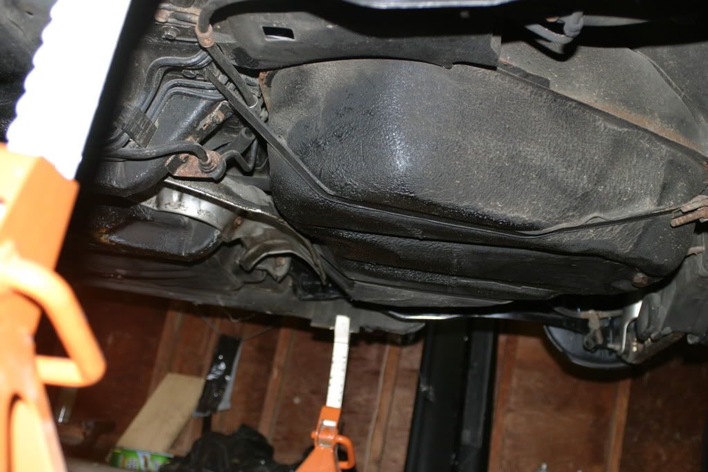
one of the first mockups of motor placement

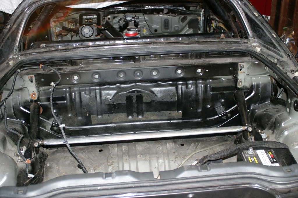
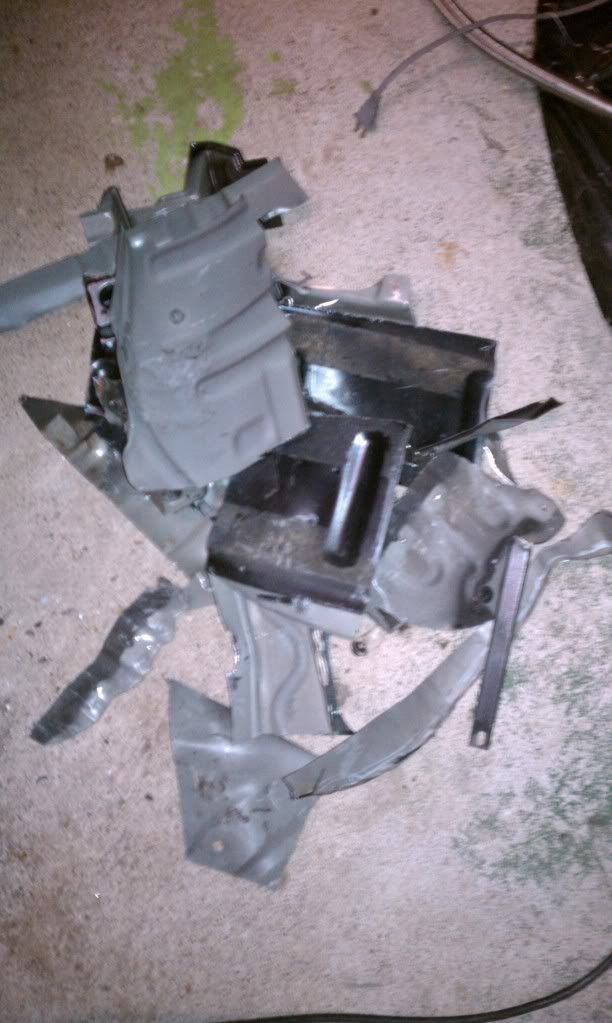
some results of MANY repeats of the mockup, mark, takedown, cut, trim, clean process
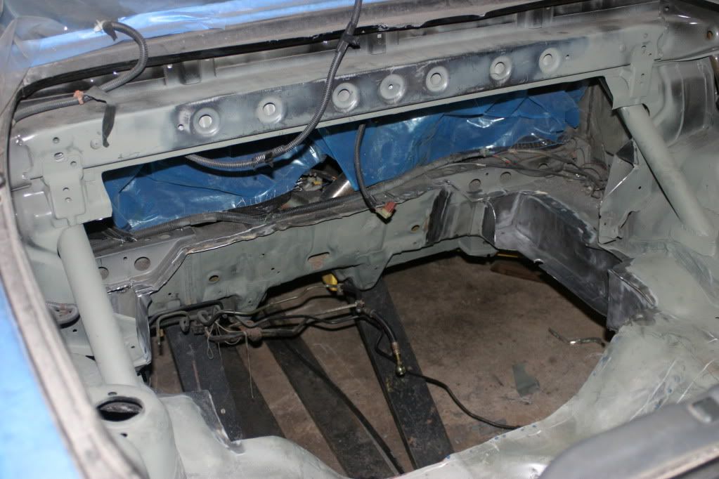
One of my goals for this project is to leave the maximum amount of factory metal in the car as possible, cutting only the bare minimum required to mount the motor. Unfortunately, the engine/transmission was a couple inches wider than the frame rails in the rear of the car and therefore would need what I’m calling “frame rail inserts” to allow me to cut, widen, and then reinforce the factory rails.
I don’t want to share too many details because it took me so damn long to piece together just the concept of them. I will say that most of the work was done by a friend of mine who specializes in fabrication for kit cars, track cars, and Porsches. Everything he did for me here came out exactly to my spec.
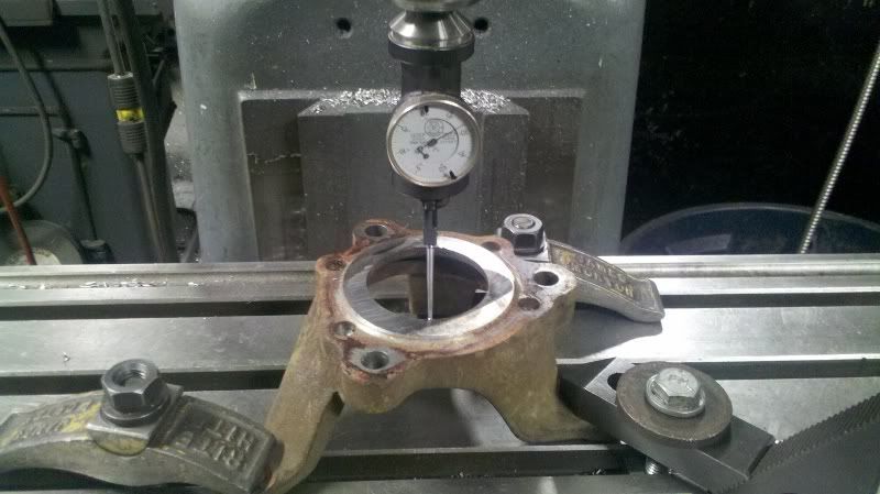
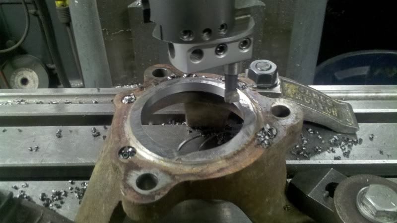
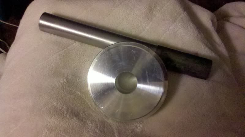
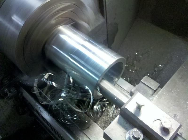
machined some parts for a fixture
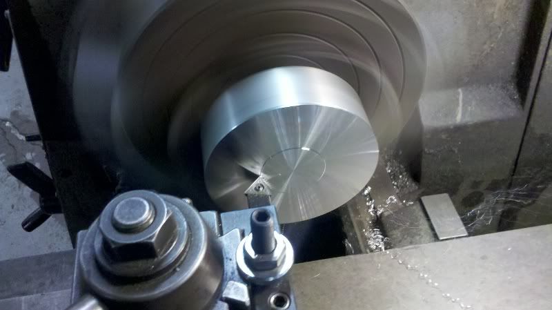
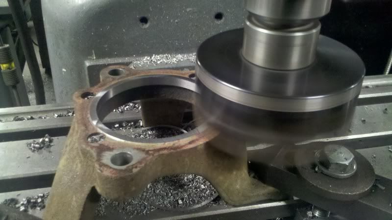
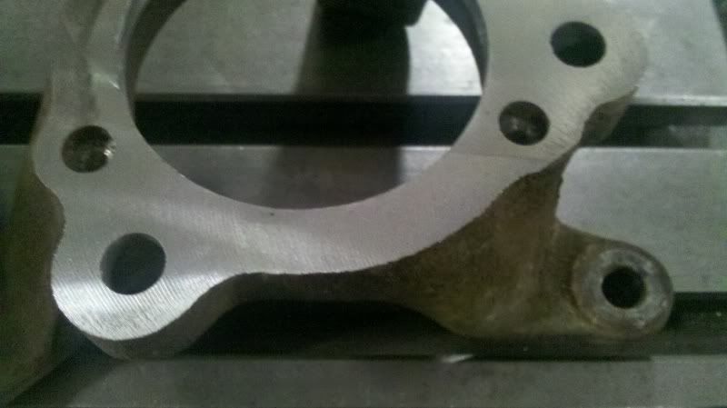
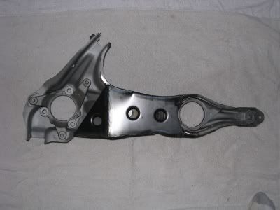
hub centric die
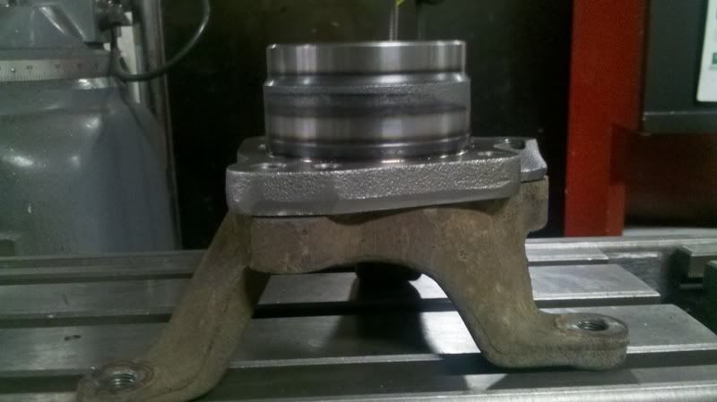
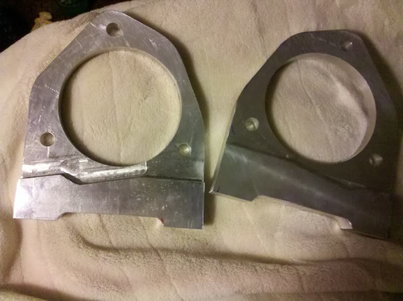
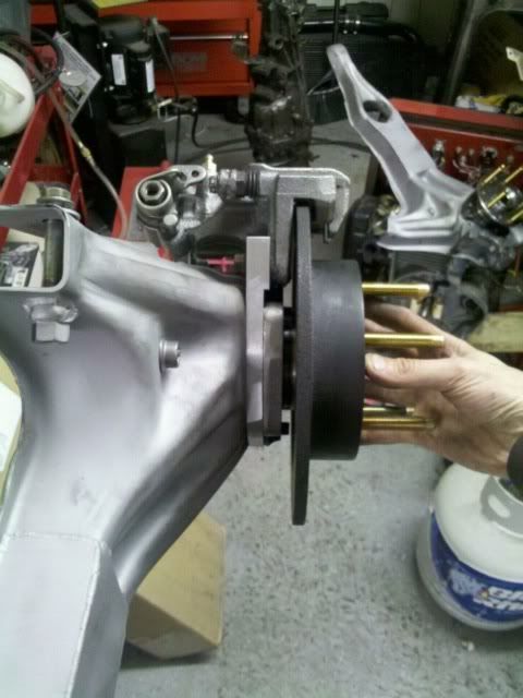
hubcentric brackets to maintain offset and mount calipers

This is crazy awesome
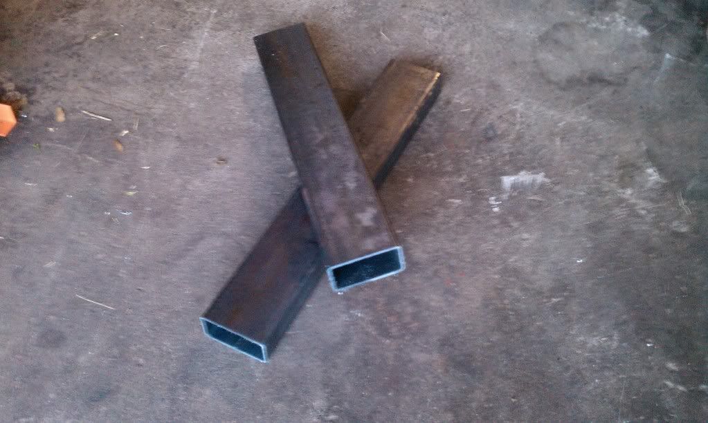
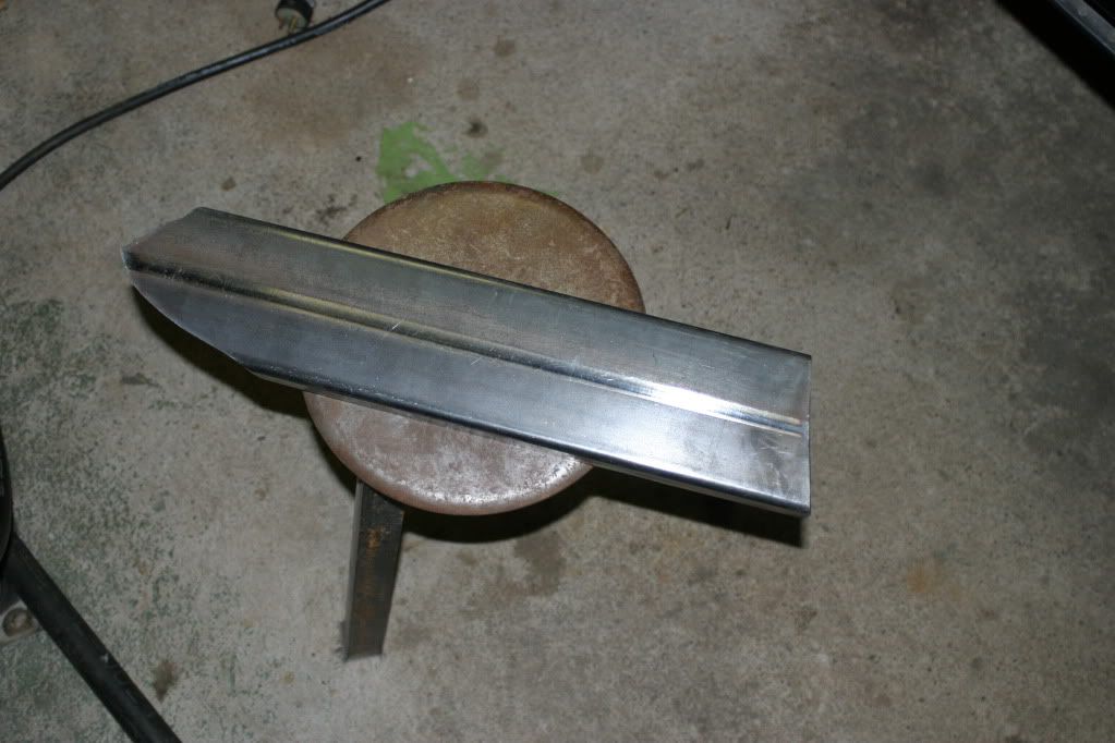
I bought two sets of structural rectangular tubing for my frame rail inserts so I could trim a set for a test fit then actually use the 2nd set once I perfected it. These pictures are the fist mockup of the first set of inserts before the concept was flushed out.
:tup:
It sucks you are gona be unable to work on this for so long 
Dan
once the concept was proven using the first set of square tubing, a cardboard template was made to the exact dimensions allowing me to not only get the most out of my practice set, but also allowing me to make sure that the left and right sides were perfect mirror images by simply flipping the template inside out.
an additional benefit is that if I smash up the chassis or need to start over for any reason, I’ll have drawings, models, and cardboard templates of every custom component made.
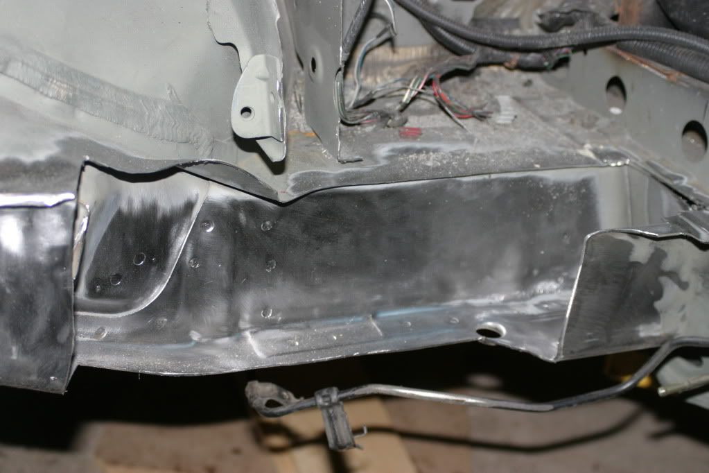
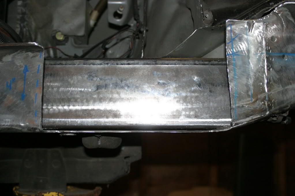
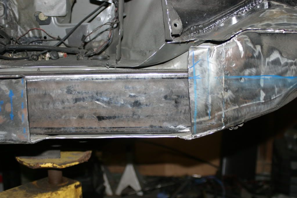
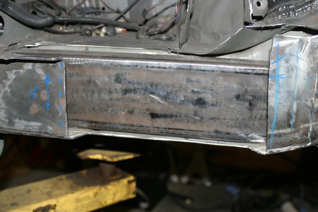
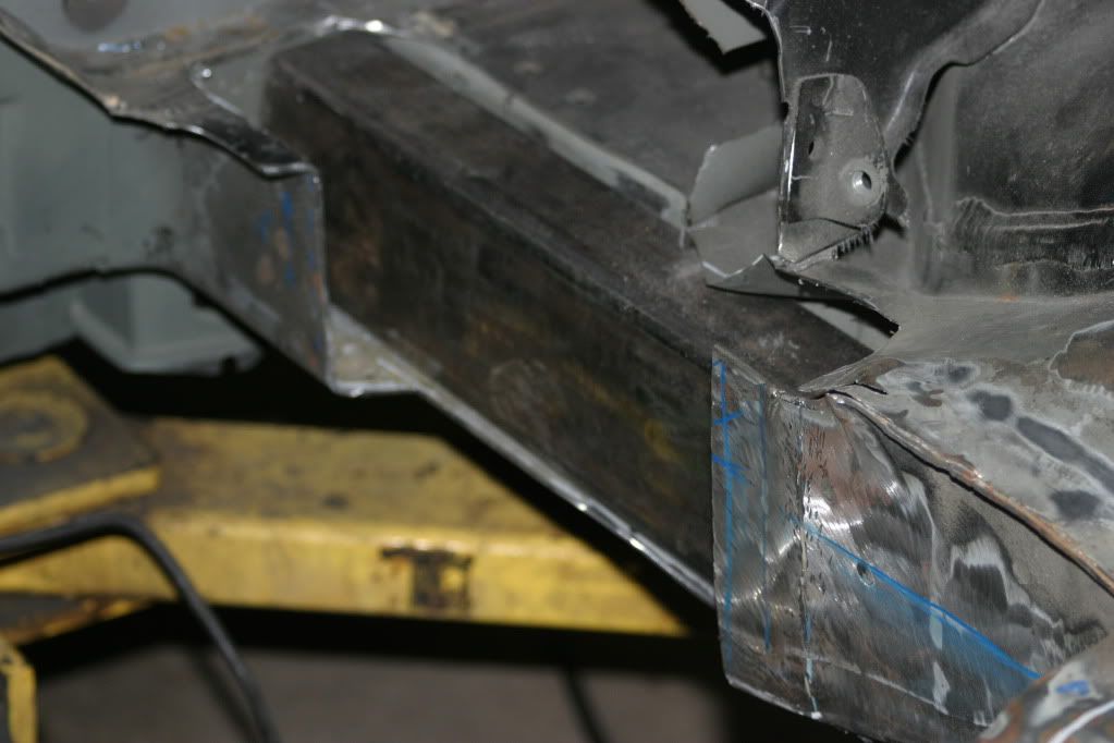
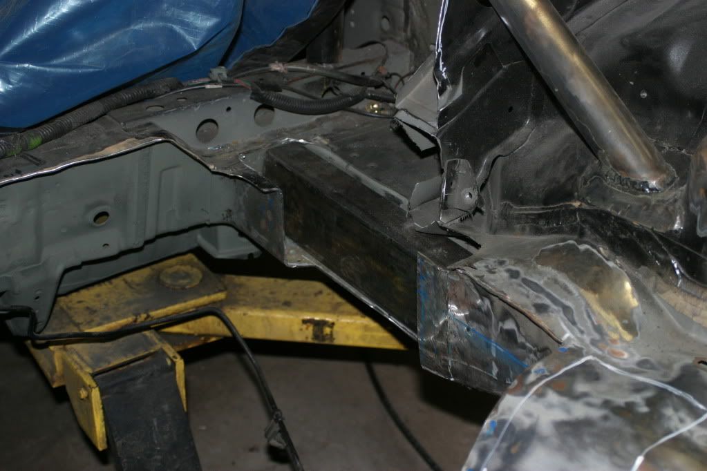
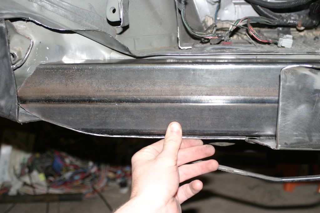
The frame rail insert after being cut to the template.
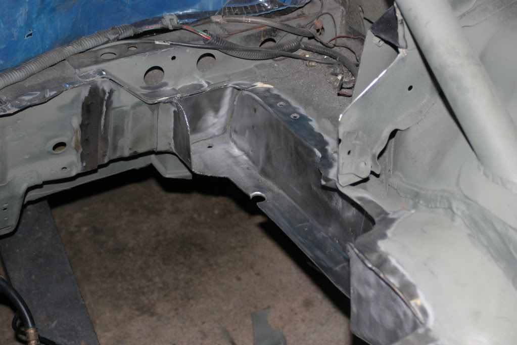
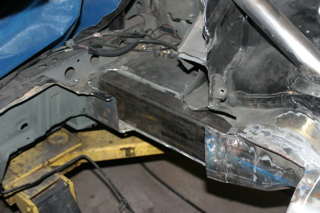
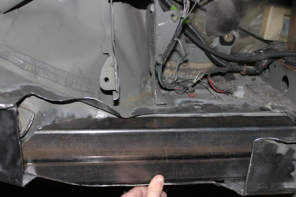
the tight and complicated fit at the back of it
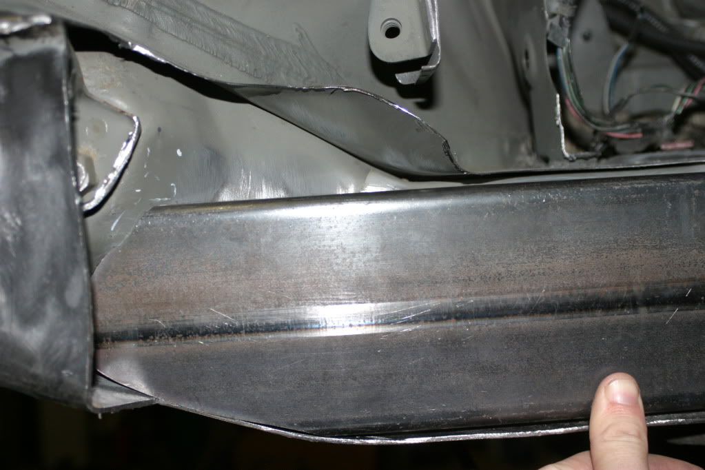
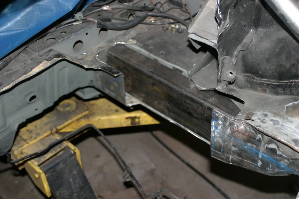
the top contours closely around the top which is the mount points for the upper control arm/camber arm
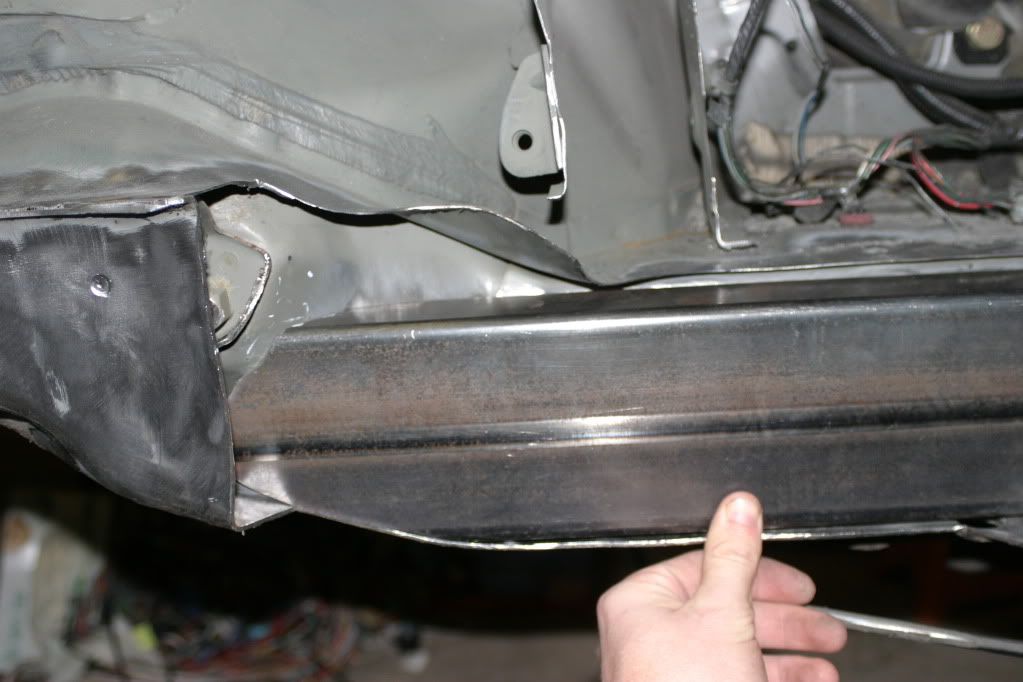
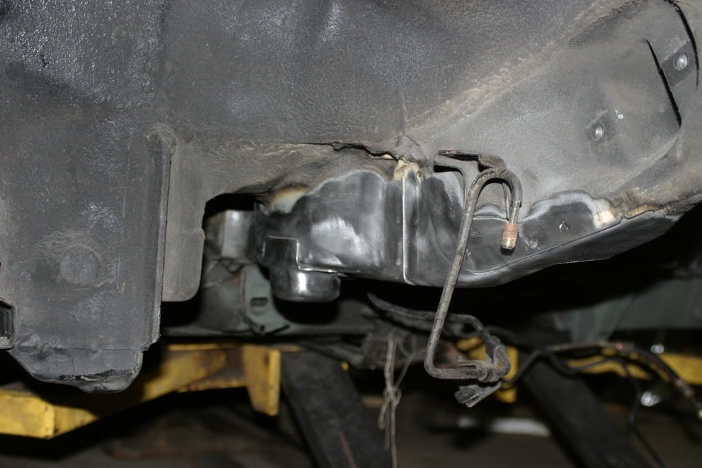
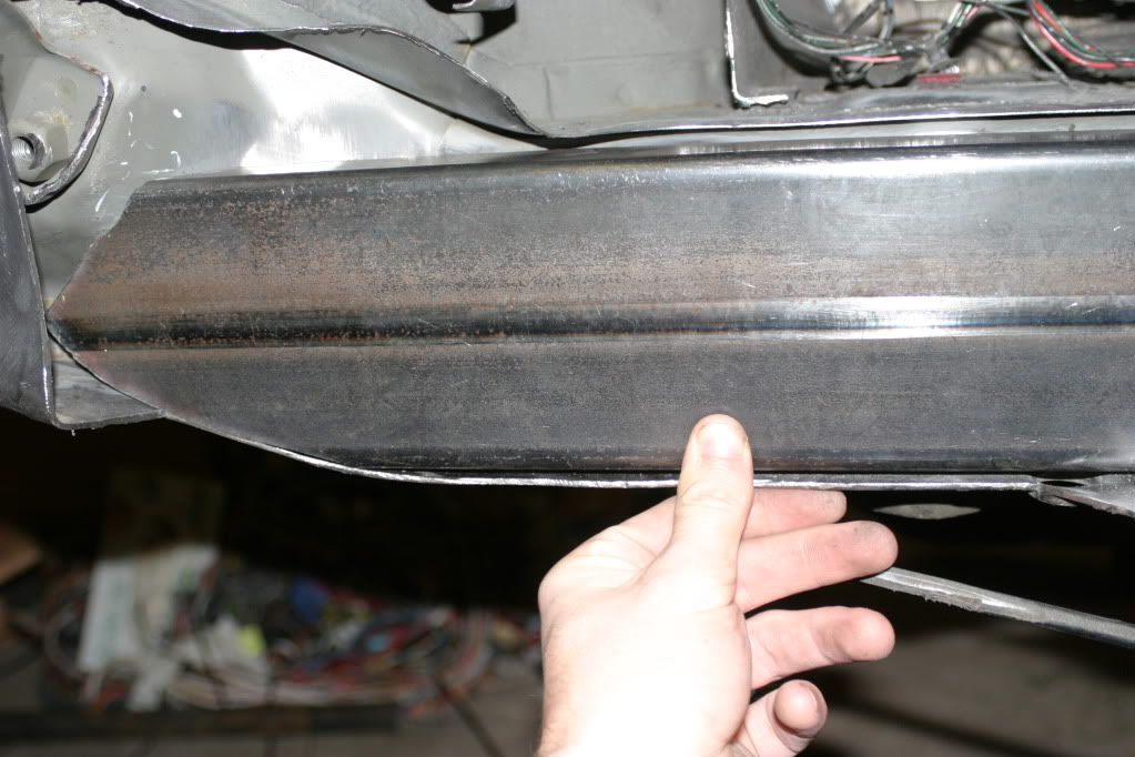
the bottom of the frame rail has a stamping the length of it that basically creates a ridge and prevents my frame rail insert from contacting the leading edge of the frame to about 1/8th inch back. I’ll need to cut a sliver of material and fill this for strength and cosmetic purposes even though the majority of the structural strength will come from the spot welds on the bottom and back side.

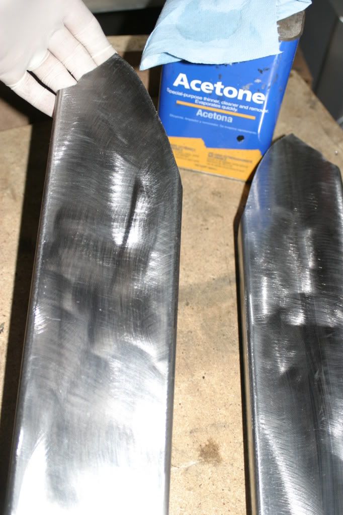
inserts were prepped with a wire brush and wiped down with acetone to make sure the welds would be contaminant free.
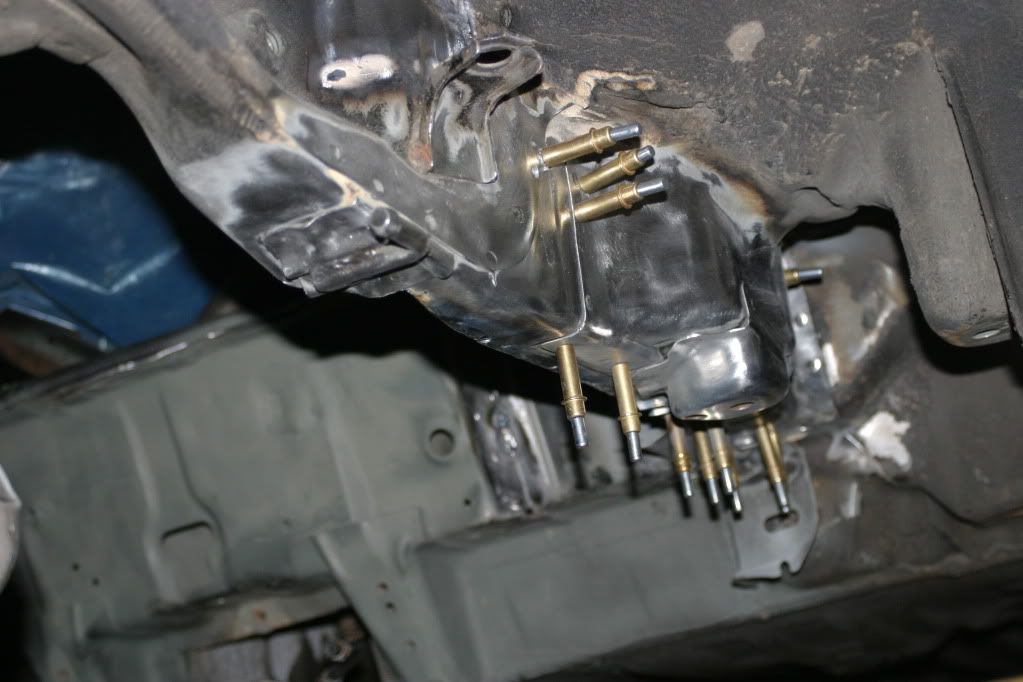
clekos held the frame rail insert in place in spots which would later be spot welds.
this… is fucking awesome :tup:
I once saw a H22a AWD del sol on hondatech when I used to have my sol. This is pretty effing awesome though. Good luck!