excellent
Hubs almost done. MF’er to machine properly. Didn’t have the correct radius cutter for the hub race transition, so I have to make one from some tool steel blank.
Just have to finish drilling and chamfering the holes for the studs on one of them. Couple of the holes are a couple thou looser than I’d like on the studs, but it’s as close as I can get it. Hole is odd size(.4675", or 11.87mm) Closest thing to it is 15/32nds drill bit. Setting up and boring the holes using a boring bar would take a days worth of work in itself so it was out of the question. You’d have $300 in machine work just boring the holes at that rate!!!
So I opted to drill at 60rpm with 15/32nds and most of the holes turned out good, couple a few thou larger as stated. Studs will now fit and will stay put once torqued with a little sleeve lock, if needed. If new studs were new the knurled teeh on the shank would be bigger and likely have a bigger bite, but we’ll see how these work first.
tomorrow is T-arm setup day 1
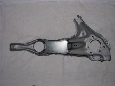
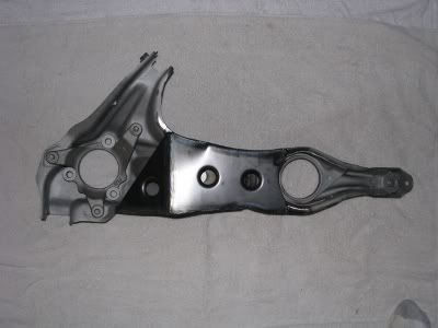
couple pictures of one of the t-arms, about 80% done here(needs brake brackets and upper arm mount relocation)
:excited
fuckin great. :bowdown
glad you approve. I hope you’re ready for the bill :lol
Starting the other arm here in a bit, just have to go get another tank of argon before they close up for the holiday.
-adam on JVG’s komputer
ha, of course. I’m working on the sketch for the engine mounts and I need to start looking at how the cantilever suspension is going to plug in. The suspension along with those LCAs are going to be important to get done so I can get the car back on its wheels before I have to pack up and move. I may give you a call to discuss that so we can figure out the best way to make this happen.
The LCA’s are not much worry for me. just sketch out what is required when t-arms are on the car and those I can make easy. I can make them from billet, but I think the best option for now is to make some chromoly tubular units with rod ends. They’d be cheap and effective and allow you to work any bugs out first. Then if wanted make a final design in billet and CNC machine them. This t-arm shit was the hard part, and only due to the amount of machine work necessary and the awkward stampings of the arms themselves. I have more time setting up and machining bearing/hub parts than I do cutting/welding. Didn’t help that the arms were tweaked a bit here and there.
The suspension stuff is not much issue. What is need-to-know is the original shock leverage ratio, the you can calculate an appropriate rocker ratio based upon your determined spring/wheel rates. The pushrod will follow the OEM shockline almost to a T, Not knowing new corner weights and the like determining the spring rate will be difficult, and thus the rockers will have a couple different ratio adjustments in them. the only hard part of this whole thing is knowing where the dampers will fit, to determin where the rocker pivots and subsequent support framework need to be. Tucking them parallel with the length of the car will give you the most room around the motor, but then I really have no idea what kind of room you have back there seeing that the car isn’t here.
One thing I will recommend you consider and implement into the rockers are Nadella combination needle bearings rather than typical bronze type bushings, or needle/bronze hybrids. The bearings can take a much higher load and will not wear/bind like the bushings do. They are needle bearings on both radial and axial surfaces. Not as expensive as you’d think.
Anyway the arms are pretty much done. Relocating and drilling the hole for the UCA mount wasn’t that bad. I opted to NOT cut and weld parts into this area to reduce the amount of weld seams, but rather trim and weld on new nuts instead. The area on the outside of the stampings will need to be notched to clear the UCA pivot, but I’m leaving that for you since you still have the UCA’s there and it should have the most minimal notching possible.
I still have to make the brackets to support the rear calipers yet. They don’t look to be overly complicated. Have to get some plate for them on Monday.
I have to total you up a bill here for what’s been done so far. You going to pay via Paypal?
Oh and I machined that engine or tranny mount here to for clearance.
I’m going to bed
sounds good adam, and yes I’m definitely going with needle bearings. I’ll pay cash or check (trying to cut down on paypal stuff after they screwed me) when you total it up just send me a message with it and I’ll get payment over to you somehow.
for the tubular LCAs, I agree that it would be the best route for right now but they will need to have the a third bushing for what was the shock mount and now will be the lower mount for the vertical shock line to the lever.
I’m welding in a 1.5" DIA DOM tube between the shock towers and I think it would work best to bring the base of the shocks right down onto it. There should be plenty of clearance all around to do that. Of course I need to do the math and order a set of shocks before I actually dive into welding any of it. What brands would you recommend for me once I calculate the spring rate?
Cash or check would be fine. I will write up the bill for it tonight. The brake brackets won’t be much more on top of it. I figure with material and machining they’ll be under $100 for the pair, which can be paid at a later date if desired.
pm’ed you
ok, some number crunching time.
assuming a total weight of 2400, but roughly a 50/50 weight distribution, corner weights should be somewhere around 600 lbs
For each corner the unsprung weight consists of:
wheel, 17lbs
tire, 28lbs
and trailing arm w/brake ~30 ??
so 75 lbs unsprung.
the front motion ratio is 1.5, the rear is 1.35
Punching it in to a suspension calculator here http://www.racingaspirations.com/?p=292 gives me:
REAR w/94 Yamaha R6 shock (554lbs/in)
Sprung Weight 325 lbs
Effective Coil Rate 410.37 lbs/in
Wheel Rate 303.97 lbs/in
Static Deflection 1.06 in
Wheel Frequency 182.4 cpm
Natural Frequency 3.04 hz
REAR W/YZF600 @506lbs/in
Sprung Weight 325 lbs
Effective Coil Rate 374.81 lbs/in
Wheel Rate 277.64 lbs/in
Static Deflection 1.17 in
Wheel Frequency 173.62 cpm
Natural Frequency 2.89 hz
FRONT W/ current 12kg/mm PIC strut
Sprung Weight 325 lbs
Effective Coil Rate 447.04 lbs/in
Wheel Rate 298.02 lbs/in
Static Deflection 1.09 in
Wheel Frequency 179.87 cpm
Natural Frequency 2.99 hz
FRONT W/10kg/mm shocks
Sprung Weight 325 lbs
Effective Coil Rate 372.52 lbs/in
Wheel Rate 248.35 lbs/in
Static Deflection 1.3 in
Wheel Frequency 164.71 cpm
Natural Frequency 2.74 hz
What I’m looking at 2 things here, #1 the front to rear wheel rate. and #2 the wheel freq in comparison to this chart:
From the Competition Car Suspension book.
60 – 80 cpm Comfortable road car.
80 – 100 cpm Sports road car.
100 – 125 cpm Racing cars without wings or ground effects.
200 – 350 cpm Current racing cars with downforce.
- 500 cpm Ground effect era cars.
As you can see I’m hovering between the without downforce and w/downforce categories here, which seems appropriate for my car although I’ll be doing more research to try to find some data from some cars that I am actually familiar with so I can put these numbers and categories in perspective.
From front to rear I want to make sure that I begin with a stiffer wheel rate in the front. This will prevent weight transfer from the rear to the front which would cause traction issues. With such a short wheel base I really want to make sure that this isn’t an issue when I first hit the road. Things can be dialed in later as I tune.
Granted these numbers are all being calculated without accurate data and therefore creating some broad adjustability in my setup is important. Basically for the front I have a variety of spring rates available which simply bolt in. For the rear, I’m selecting motorcycle shocks that are already setup for a cantilever w/needle bearing eyes and have a variety of spring rates for similar lengths. The bell crank will have a few different ratios to allow me to adjust that as well.
Anyway, still all work in progress as I learn how to decipher the data. If anyone notices anything that may be incorrect, please for the sake of my education on the subject speak up.
I’m trying to find out if I’ll have sufficient suspension travel with the shock that I’m prepared to buy but I can’t seem to figure out how to calculate transmissibility. From what I understand I should be able to figure it out from the mass, spring rate, and damping ratio. But maybe I’m wrong, anyone know anything about this?
Total travel or compressive travel?
Total travel is simple with just motion ratio, rocker ratio, and total damper piston travel.
Compressive travel factors in suspension droop on a settled car, which get’s a little tricky to get 100% but is including mass factors and springs rates.
Since you are going to be making the rear damper mounts suit the desired range of ride height for the car, you simply need to factor the direct shock travel under droop for the calculated load on your determined spring rate, then factor that figure into the formula for determining the leverage over the shock with the motion and rocker ratios(geometry)
total travel, yes. I can calculate that easily as you said, but what I am trying to figure out is resulting travel after inputs such as bumps, accelerating, and cornering… right now I’m on bumps though, I have some formulas for accelerating and corning, but the simplest, for bumps, my search is coming up blank.
What I want to know is if the the shock travel that I’ll have will be enough to cope with the demand or if I’ll be hitting the bump stops on a daily basis.
Bumps are considered high speed moments, and most of this is built into the high speed valving formulas for every shock manufacture.
Shock travel should always exceed suspension travel and the bump stops should be a limiting factor in the travel. If the suspension travel exceeds the shock piston travel you risk damaging components, regardless if there is a bump stop in there beforehand. You should be calculating total wheel motion with the max damper travel and if that doesn’t suffice the cars needs, then you have to consider other dampers before figuring out all these rates.
I had a funny feeling that the bike dampers would be bordering too short on travel for this setup without having to run some rediculous rocker or motion ratio to compensate.
You also need to consider piston speeds with the desire ratios in effect. Too slow of a speed and dampening suffers, too high and you can overheat the damper and fluid, or cavitate the damper and lose all dampening function. This is all int he ratio, and in the rear we can tune it with the rocker ratio.
absolutely… I’m just trying to anticipate the max travel so I can confirm that the shocks will meet the car’s needs. I’m just not sure what formulas to use.
That’s all based on the variables of the shock dampening, valve rates of the piston, dampening fluid weight, fluid and damper temperature. etc. You may have to contact the manufacture for some of that information if it’s preset/non-adjustable from the factory. Shock dyno charts, etc.
.
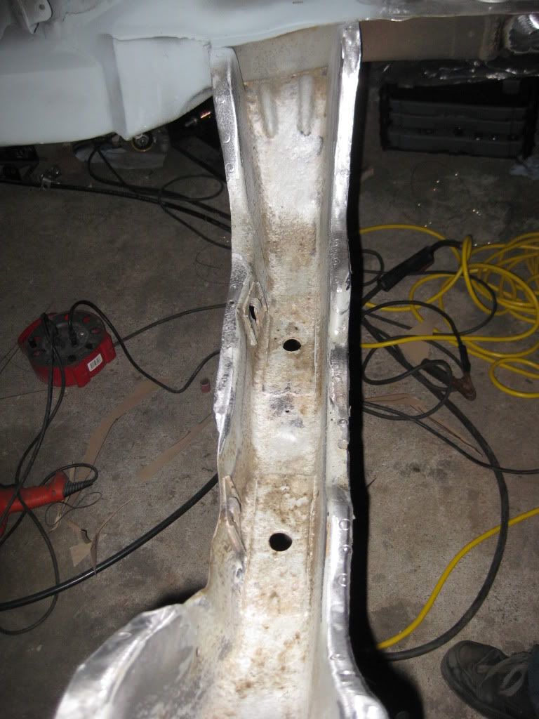
progress finally. Its annoying how much time I had to spend grinding out contamination and fixing it all, but I finally have strong welds and what should be a very solid frame rail.
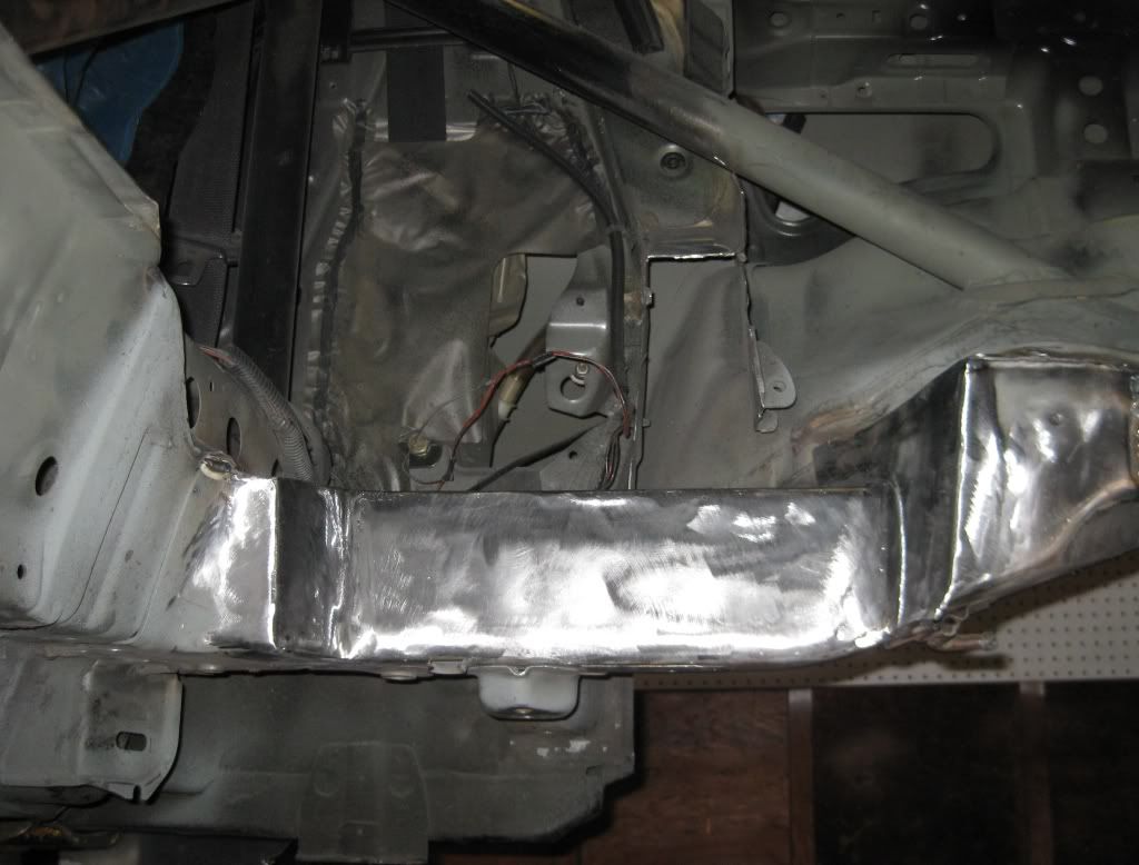
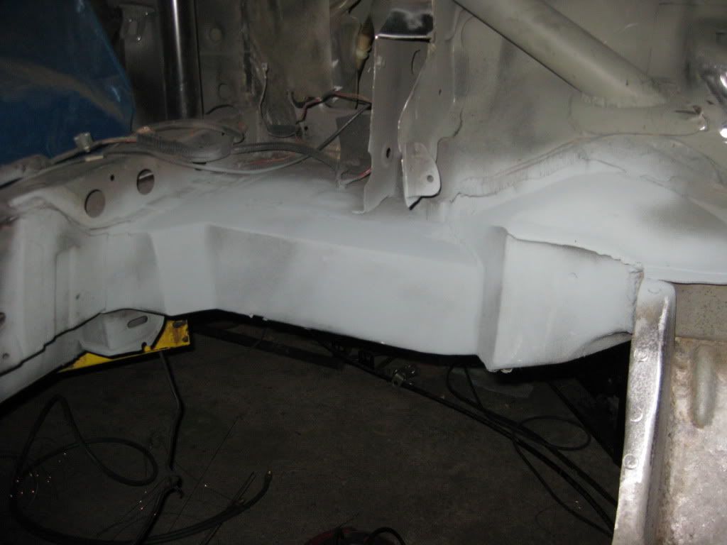
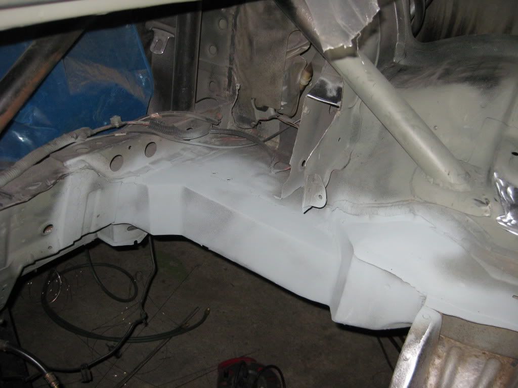
and I finally have a master plan for this:
The 7075 and 4140 billets arrived for your spacers and hubcentric rings(for the spacers). Yay. Might actually finish these up next week.
ah, good. getting close to crunch time here. Last few parts I need are coming in and I’ll have mounts made up very soon.
indeed. That other mount you gave me is machined/notched as you wanted. Just need to debur the cut.
I’m making the spacers/bracket from a single piece of billet, then turning chromoly double hubcentric rings that press into the bracket/spacer. weeeeeeeeeeeeeeeeeeeeeeeeeeeeeeeeeeeeeeeeeeee…
Needless to say, lot O’ chips to be made.