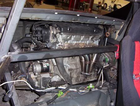
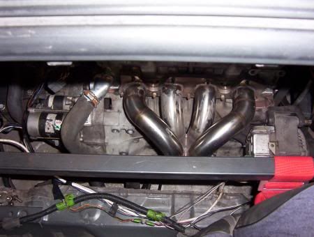
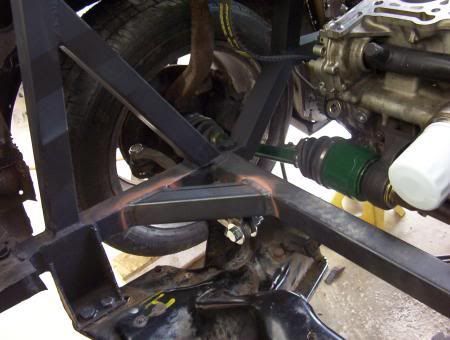
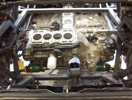
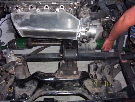
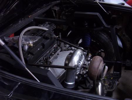
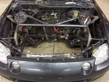
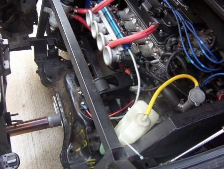
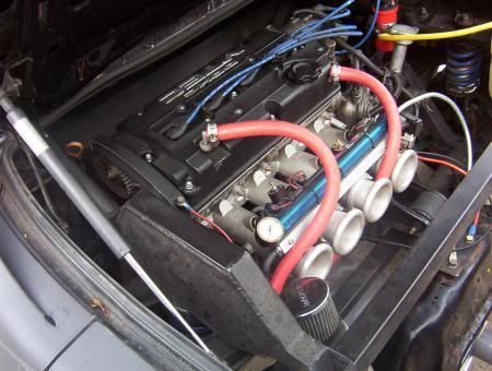
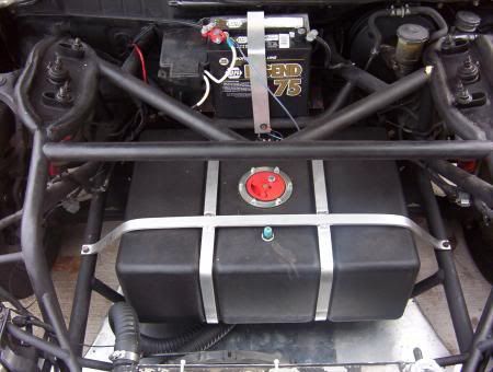
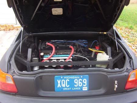
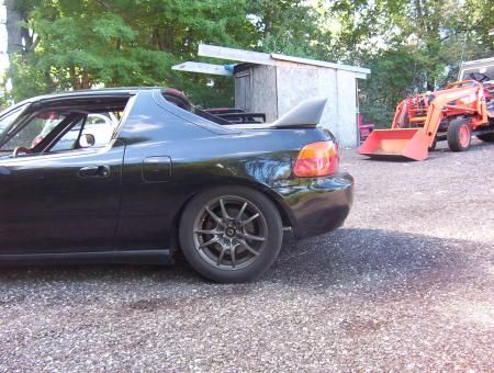
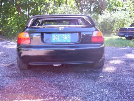
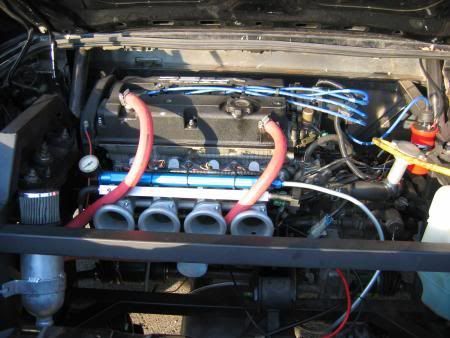
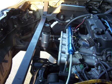
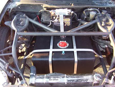
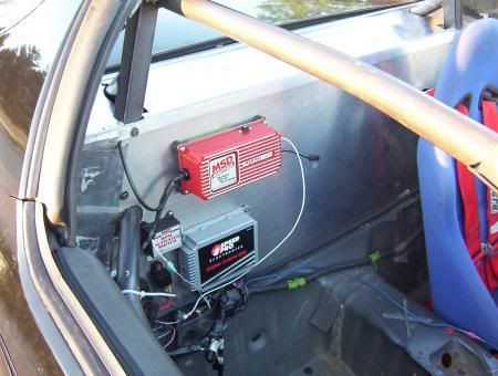
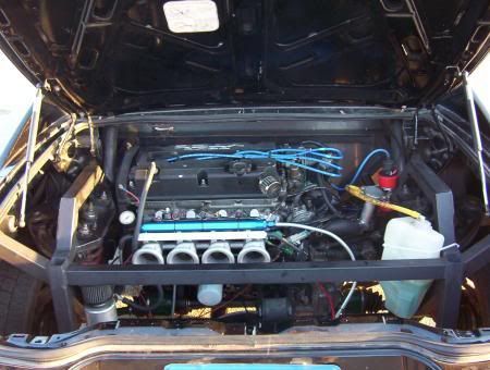
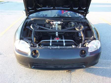
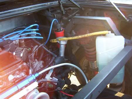
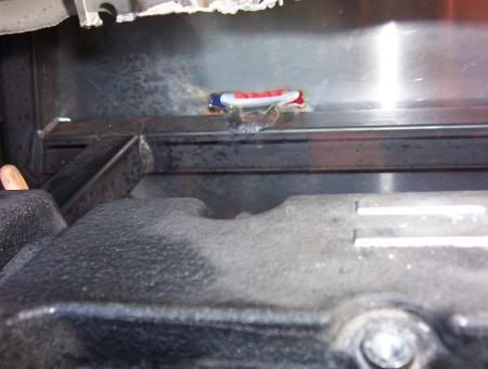
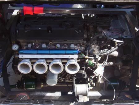
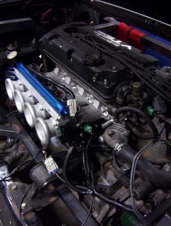
I finally found some cached images of the LoveFab del sol with the Prelude H22 in the back. It started off as a smashed car that they just wanted to dick around with but it ended up being the first rear/mid engine sol with a documented build
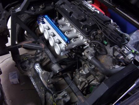
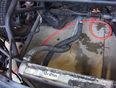

I finally found some cached images of the LoveFab del sol with the Prelude H22 in the back. It started off as a smashed car that they just wanted to dick around with but it ended up being the first rear/mid engine sol with a documented build
wow that thing is cool… when was that built?
If I remember correctly '04/'05
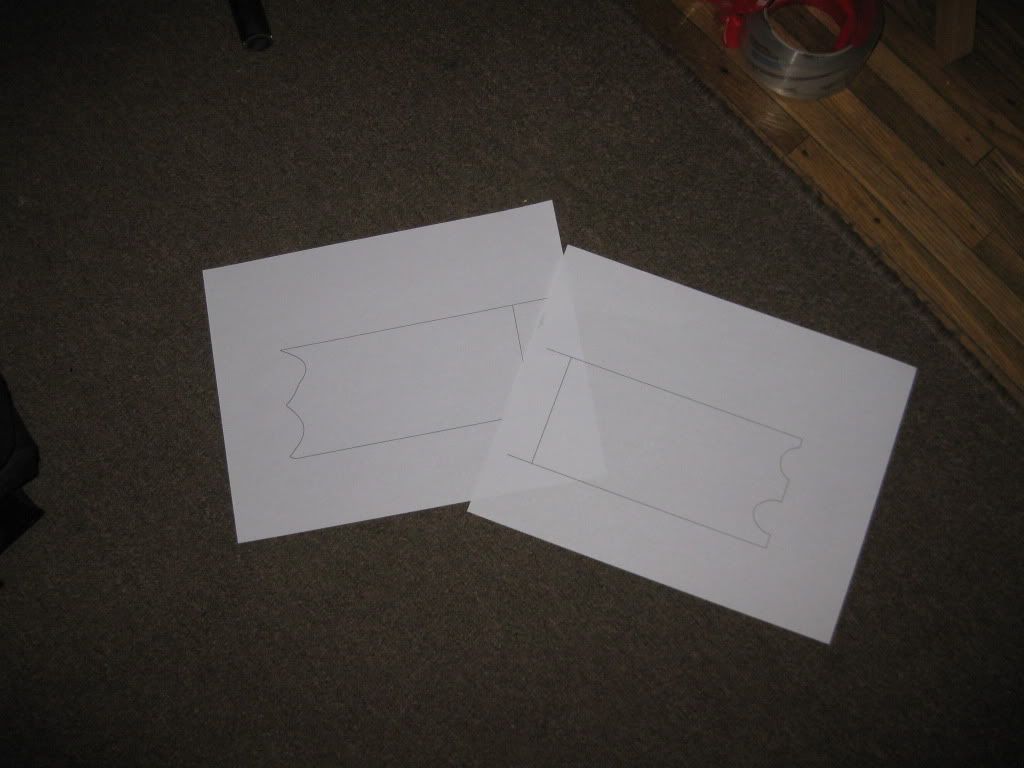
I’ve finalized my solidworks drawing for the additional support bars and tried out a new method for getting the cuts correct
simply made an .1mm extrude down the length of the tube and then converted it to sheet metal. Then flattened, and added to a drawing at a 1:1 scale. It didn’t fit on one paper so I added a center line so I could tape them together and have the correct length.
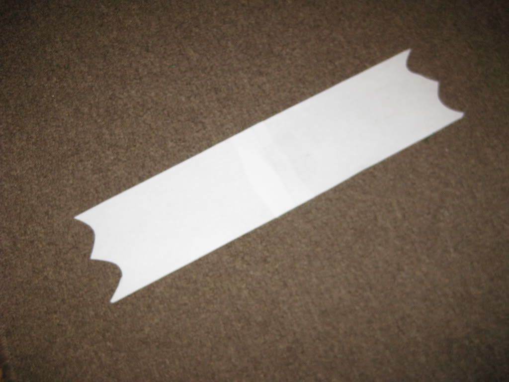
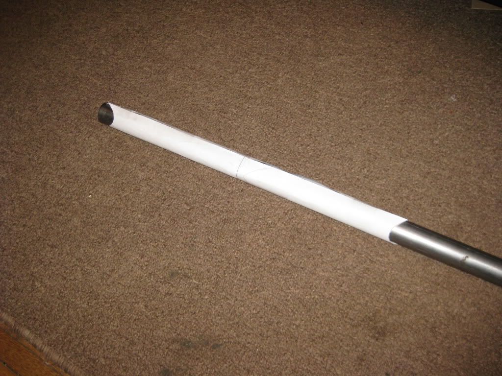
Simply trimmed them out and taped them together, wrapped them around the first bar and traced my cuts, then flipped inside out (bars are mirror images) and put on the other bar to do the same.
Wile you’ve been busy playing with paper I’ve been cutting your parts :tongue (actually is a good idea, I’ll have to keep that in mind for some shit here)
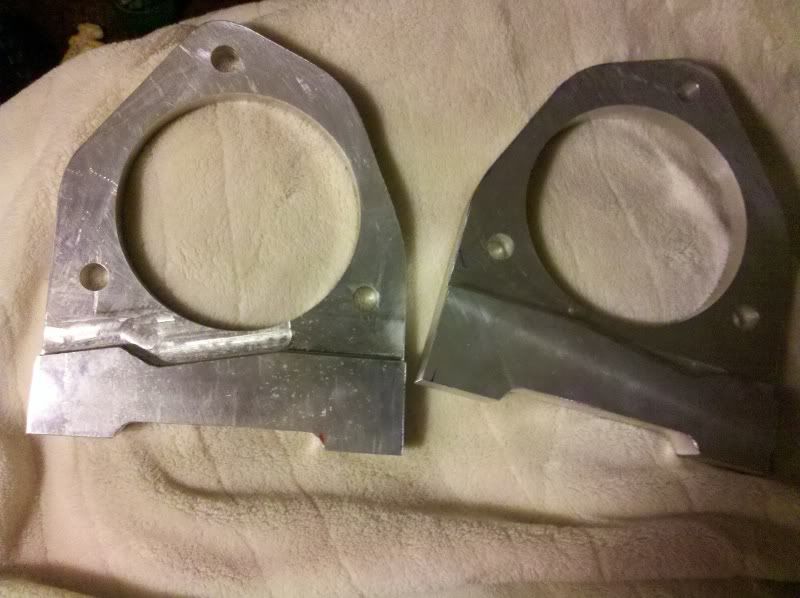
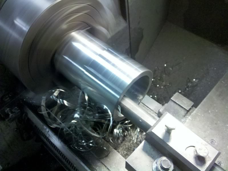
Did a 'lil bit of this:
Ended up with these. Still need to drill the caliper bracket holes and then deburr and blast them @ 400 grit.
Also cut the extended hubcentric rings from a piece of 4" chromoly. My ears are still “singing” from the cutting. Unfortunate to waste a $40 piece of billet just to make these rings, but it was a necessary evil. I dislike cutting this metal because it doesn’t produce chip, but rather a continuous thread of RAZOR sharp metal. The danger lies in that it’s difficult to break up and hard to keep away from the head. If it get’s caught in the head while cutting, it can be very dangerous. These rings are now welded onto the spiders and slip fit into the register on those bearing spacers/caliper brackets.
I still have not got a quote to PC them as I think I may have to make some small nips or notches for the caliper bodies to clear, but won’t know for certain until I can get them all bolted up solid.
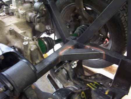
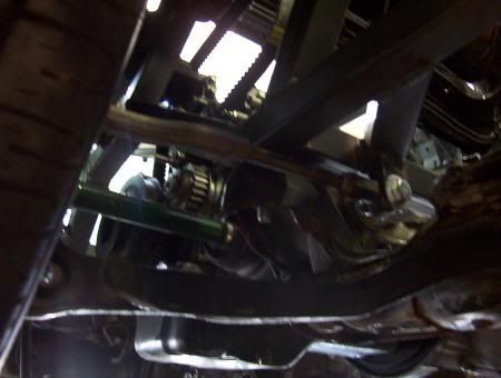
All coming together on this end though.
we’re going to have to skip powder coating and just paint it so it won’t rust. I have less than 10 days before I need to move the lift out from under it.
also, can you get me the offset that the LCAs need to be so I have have something rigged up just to allow me to sit it on the ground.
For the paper tube template, If your welding onto a bend I really can’t think of another way to do it. This seems simple enough and should be pretty accurate. My only question is whether or not I’ll be able to align the cuts perfectly from the outside wall to the inside.
I should have the arms done completely done tomorrow, so I’ll get a coat of epoxy primer on them and then shoot them black.
I didn’t record that dimension, but I can just bolt up the original spindle end of the DS arms to the jig and take that measurement no problem.
I have my methods for doing the rollcages and tube chassis and have some laser alignment gear that makes mirroring the parts simple. The paper roll trick is just neat for the stuff like this subframe and/or a-arms. I’ve done the 3d-to-sheet effect on things like boxes and tanks, just never for round tube with notches.
awesome great. I just realized that I have a junk set of stock arms that I could throw on in case of an emergency. Its good to have that option since after I get the modified trailing arms I need the cantilever suspension and some sort of offset LCA in order to get it on the ground.
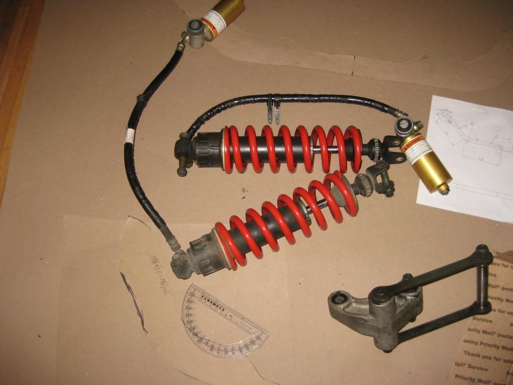
The good news is that my 2nd strut came in. I think I forgot to mention earlier that I have not actually decided on exactly what shock I want to use. I just picked one that was the correct length (the most common shock length), and that appeared to be correct by my calculations. Once the car is running I may buy a few different ones and/or have a custom set made.
You’re just planning on storing this in a garage for the time being right? If that’s the case don’t rush the canti setup, just make solid block legs that replace the struts and it’ll support the rear solid, enabling it to be moved around on it’s wheels just fine.
This is true. Although I think I have found a way to keep working on it for 5 more months. Just need to find a way to get it to Georgia. lol.
Lol
Nice to see real deal work going on up in here.
for making wrappers for tube notches…
http://www.metalgeek.com/static/cope.pcgi
you punch in your 2 sizes of tube, angle that they join and any offset… then it spits out the pattern that you can print from a .pdf
handy for quick things you don’t want to model in cad. I mostly just used a chop saw to notch for my cage, but for some of the steep angle nodes, I used a wrapper so i could trace the notch and cut it with a grinder.
Thats freakin awesome!
surprised you guys don’t use these

I do, I have two in all sizes from 1" to 1.75". I also have lasers with aluminum inserts I made that fit inside their ID’s for tube positioning over long spans ![]()
fucking PC They don’t work at all though on copes near or on radii, or anything well once you extend the pins beyond 2" though. The mark become shit at that point and getting the cope cut tight becomes a chore.
I used one of those for some of my build.
nice tool, but It was borrowed from a friend that didnt take care of it very well and the pins were rusted up :banghead
If you do alot of copes as it’s picture they work fine, but if you are into complicated nodes and steep angle copes like you find on tube chassis and big cages, they’re pretty much useless.
I’ve got ~$700 into full sets here and definitely have NOT got my money back out of them :lol
I definitely had a bunch of easy ones on my cage, but they were simple enough to just use a chop saw notch :lol I tried to keep the design simple since it was my first cage
there was a couple where the halo meets the b pillar hoop that were very tricky though. the node was on a bend on BOTH parts :nuts
Good shit, it was actually more work than I’d like to get it to come out right in solidworks. I’ll have to play around with that next time.
interesting. Looks like another one to try out at some point.
lol, I meant the only way for me to get it done. I don’t have any of that fancy laser stuff. :tongue
What have people used for making the cuts? I ended up using pretty much everything in my air-tool in my arsenal but i’m sure there is a better/cleaner way to do it.