car on trailer, behind uhaul, behind snow plow… It was a rough ride down to GA. You’d seriously cry if I posted pictures of what the car looked like at the end of the trip. All the newly fabbed stuff was in really rough shape.
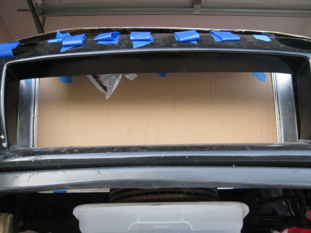
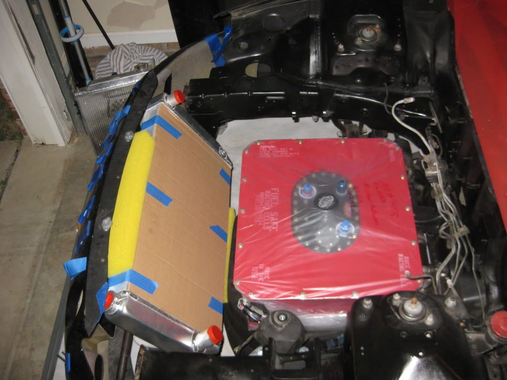
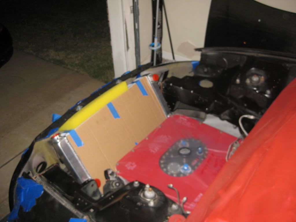
I finally ordered a radiator, went with a griffin 16" high, 31" long, 3in thick one. Those dimensions put it just a bit taller, wider, and thicker than my radiator so it will be able to be mounted a bit more in the nose of the car with the majority of the area in direct contract with the air flowing through the bumper. This will make it easier to create ducting and direct air flow under the hood.
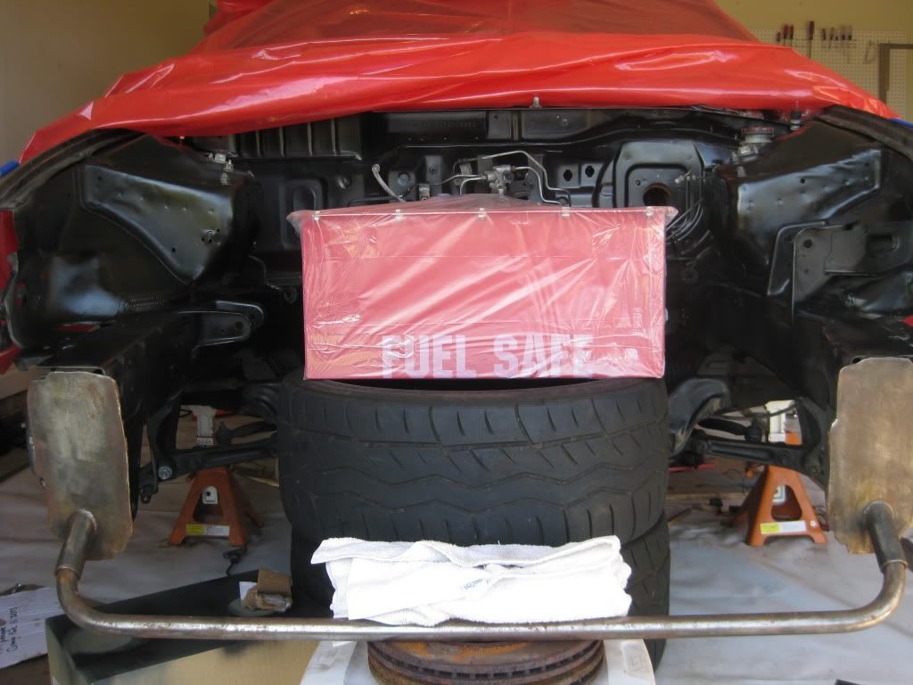
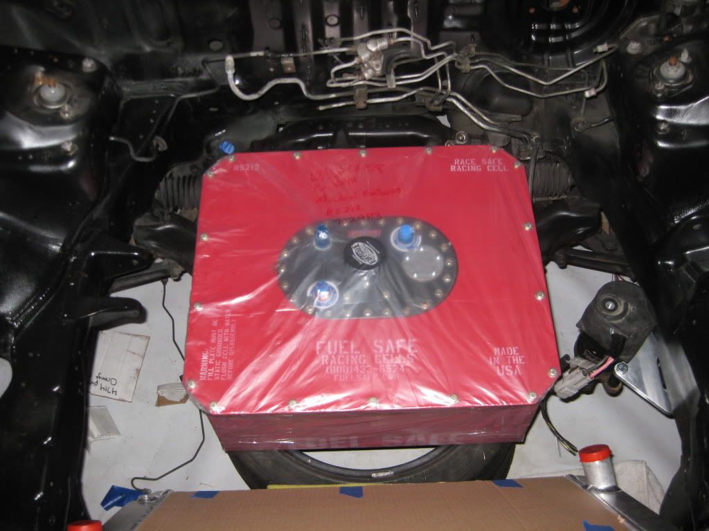
I’m still waiting on the 12g fuel safe cell to come off back order. Once both are here some more fab work (mounts and brackets) can be completed.
It’s often cheaper and better to just have FS or ATL make you a bladder, then just make you own cell can. Can use their filler necks or make you own. Tis what I did for the subaru.
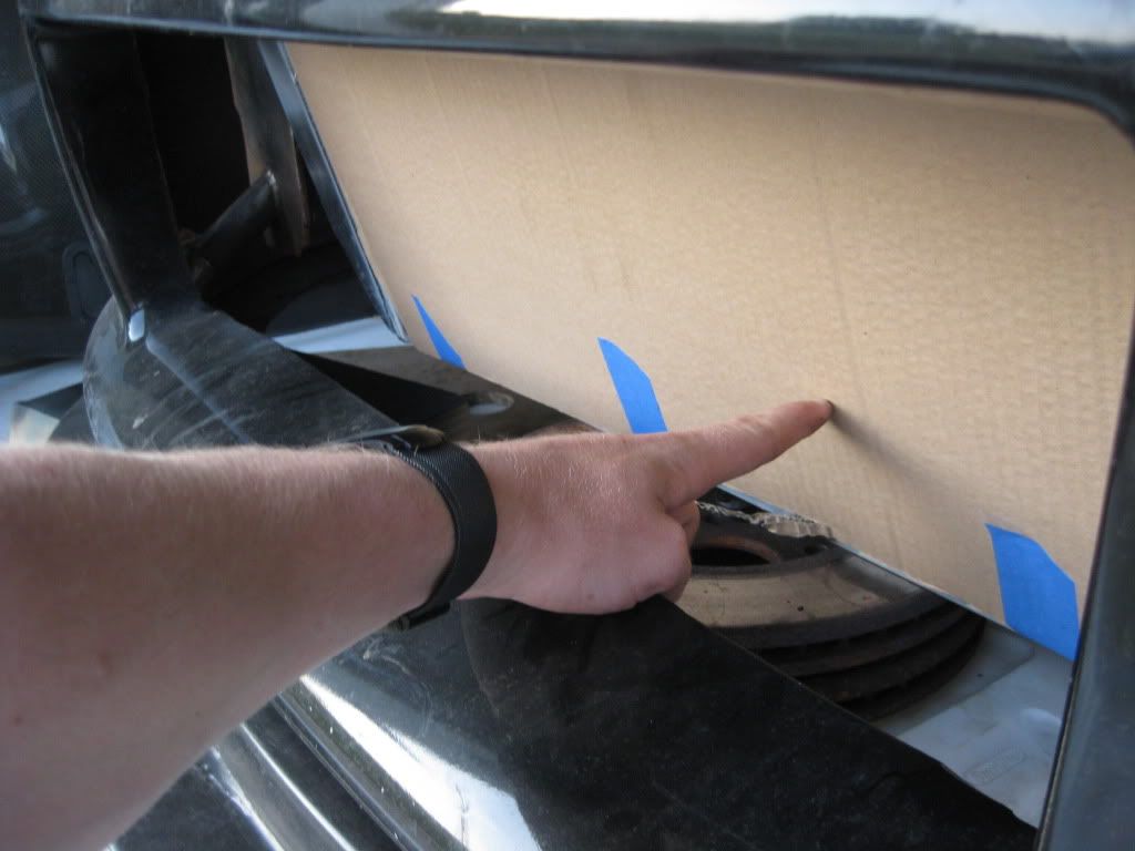
Remember when making radiator ducting…initial opening at front of ducting should be smaller and have the duct work taper up to the core of the rad. Cuases high pressure at the front opening and low pressure on the backside, airflow slows down over the core and absorbs more heat. People just assume that a shit ton of airflow across the core is always the best move and it’s not always the case. If the heat can’t transfer to the air it’s not going to do much. IIRC, quick reference to the formulas are in C.bells Max Boost book.
what I have in my head should abide by those principles, but I should go over the formulas and take some measurements once I get it in to be sure instead of just guessing.
so true. If you have any idea how long it took me to pound that into the heads of fucking computer nerds on the overclocking.net fourm!!! Talking liquid cooling PC stuff, same thing really as a motor… they all though “woot massive loud high speed fans, high mega crazy flow pumps in the system” were the best. Not the case, if the heat sink flys so fast past the heat, how the hell will it work?!?
I think I made the example about the air chamber you stand in for 30 seconds and the fans blow dollar bills all over the place and you have to catch them. You are the radiator and the dollars are heat. With their thinking they would come out of the game with empty pockets. If the air slows down its easier to catch the money!
Its just that once you slow it down too much where their isn’t enough air flow to wick the excessive heat from the system, when more is better. But when 10+ cfm would get the job done, slapping another 800cfm 12" fan would be a waster of energy, and technically speaking power from the car.
what chapter are the formulas in? i only found this part about placement/ducting. Technically about intercoolers, but heat exchangers anyhow:

Ducts.
A duct is in a large sense, a form of streamlining of the core. The ducts present the air molecules with no alternative but to go on through the core. Do not underestimate the ability of a duct to improve the efficiency of the intercooler I would suggest that an improvement of 20% is possible, good duct versus none.
When constructing ducts, it is decidedly worth the extra effort to insure that the air molecules have no alternative hut to go through the core. That is, seal all edges, corners, and joints.
It is not necessary for the duct inlet, to be as big as the frontal area of the IC cure. A rule of thumb is that the duct inlet should be at least one-fourth the core area. This rather strange situation is brought about by the fact that less than one-fourth of the air molecules would get through the core with little or no attention to ducting.
Core streamlining.
Streamlining represents the ease with which ambient air can get through the core. Certainly, the easier the air moves through the core, the greater will be the rate of flow and, hence, the greater the cooling ef¬fect For example, if the charge air tubes in the core present a rounded edge to incoming ambient air, the rate of flow is likely to be somewhat greater. An en¬gineering factor missing from all core data published is an ambient air drag co¬efficient.
Placements of the intercooler.
The place to put an intercooler so often boils down to finding available space for a big enough unit. That doesn’t take much science. A few rules, however; should receive some forethought. Try hard not to put an air/air intercooler in the same compartment as the engine. Placing it behind the cooling system radiator is also out.
Consider that air having passed through the cooling system radiator is generally 40°F or more, hotter than am¬bient and therefore does a lousy job of trying to cool anything.
Indeed, the turbo, in low boost ranges, may not heat the intake charge up to the temperature level of the underhood air that is being asked to cool the in¬take charge. When this happens, the intercooler becomes an “interheater” not a good turbo part. When the boast rises to the point that the temperature of the charge exceeds the underhood temperature, the IC will begin doing some work but will forever suffer from a severe efficiency loss. Not what we want. Underhood radiation of heat to the IC can also be a problem. Insulation and ducting can help these problems, but, fundamentally, the engine compart¬ment is no place for an intercooler.
** RULE: Always be on the lookout for the villain called the “interheater”
oddly enough it also says a thinner core is more efficient. I could have sworn I’ve read otherwise elsewhere. I’ll have to look up and find out who it was.
some more reading/banter on the topic:
http://fsae.com/eve/forums/a/tpc/f/125607348/m/776106224/p/1
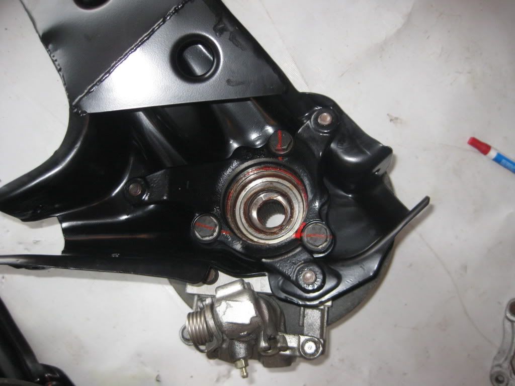
Revisiting the trailing arms now that the bolts have soaked:
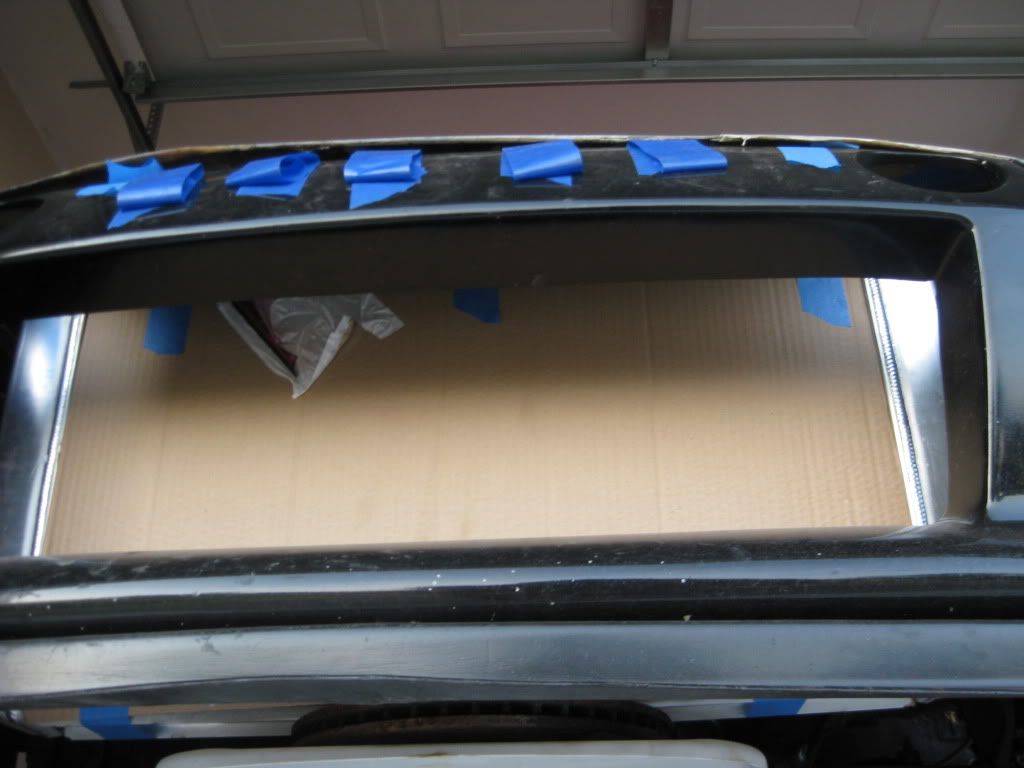
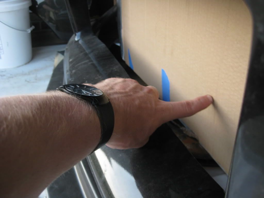
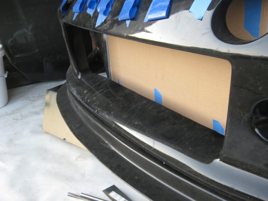
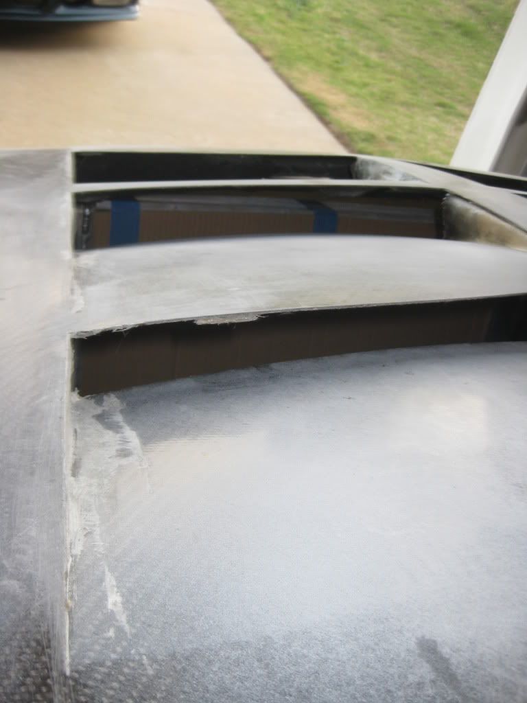
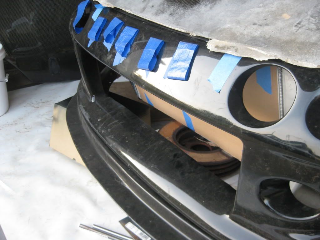
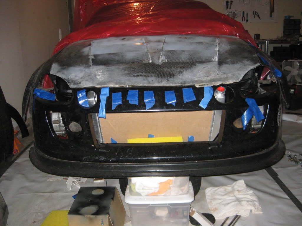
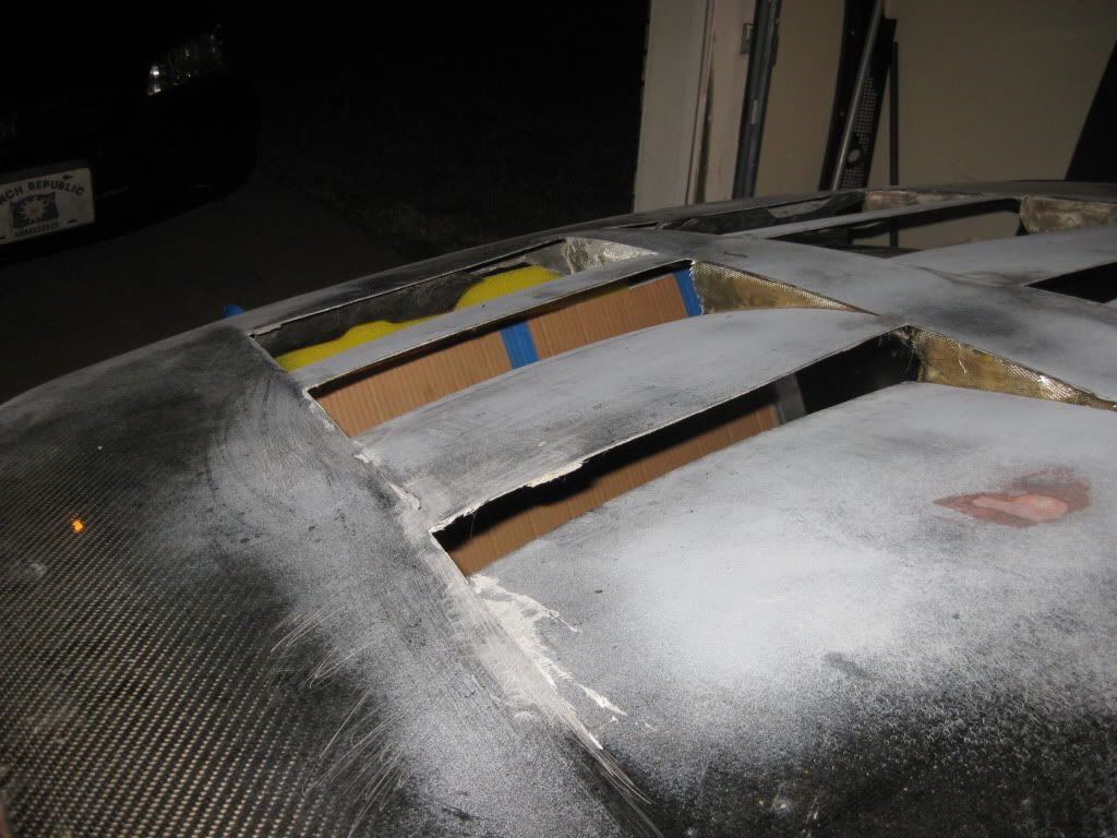
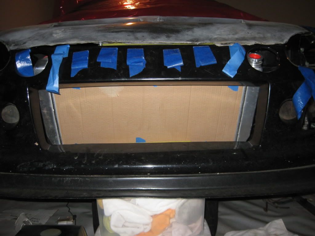
checking radiator fitment and mounting options:
vertical mount:
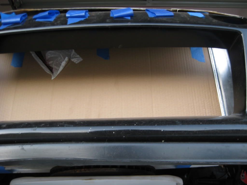
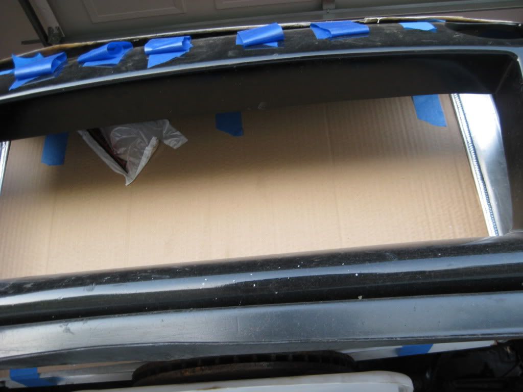
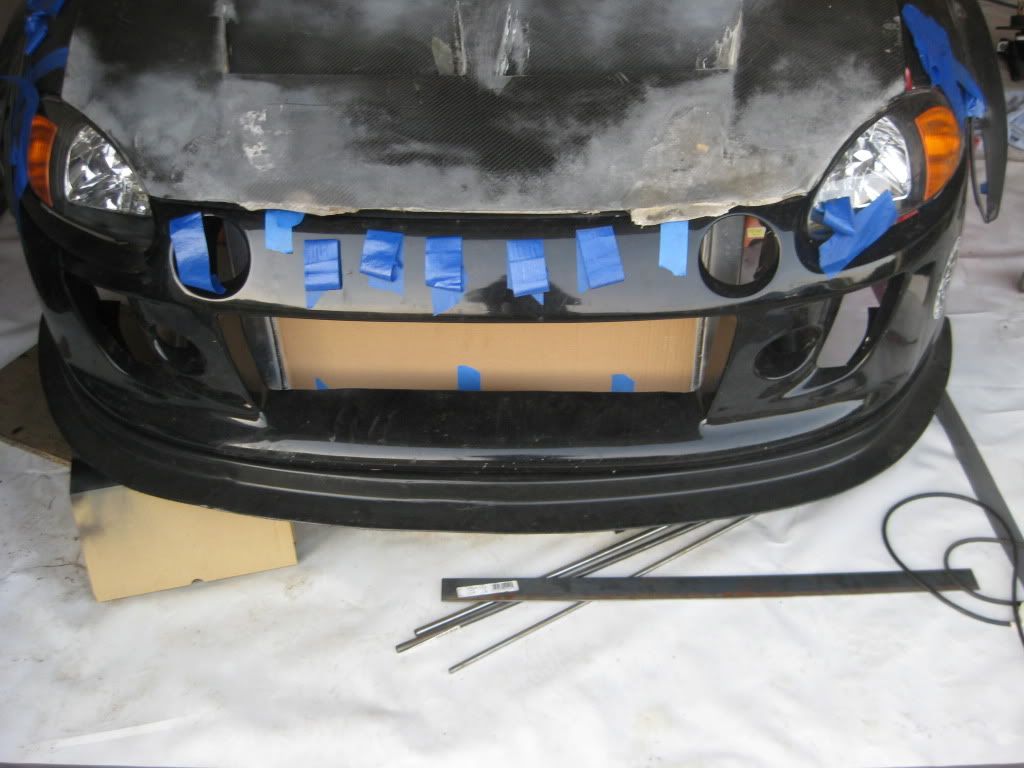
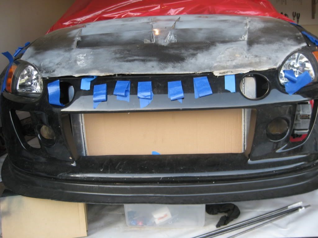
tilted at an angle:


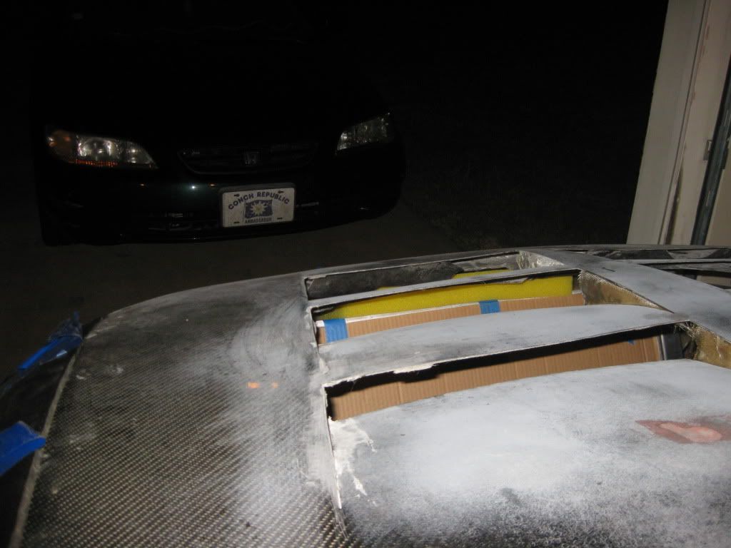
Front end looks good
It really looks fantastic with the shaved bumper and wide wheels on there, but it will be a while before thats all back together again.
Any updates?
trailing arms mounted, and this came in:


I should be able to mount it about an inch lower and an inch farther back than it is now.
Adam, You have a PM. Hopefully I can send you specs for LCAs soon.
That fuel tank is badass. Keep up the good work man :thumbup
thanks, doing as much as I can every weekend.
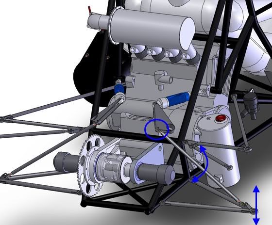
I’m still working on the drawings of the control arm and suspension linkage for the canti setup. I’m trying to figure out the rod ends though;
I don’t understand how in a setup such as the one pictured below can work properly without the linkage rotating/pivoting on the circled heim joint rather than pushing on the bell crank in a linear fashion. Can anyone walk me in on this?
Also worked a little bit more today on finalizing the engine mount design but I know have two options I’ve drawn up. 1. like I designed a few pages ago, mounted on my frame standing up. and the new design: 2. tabs hanging off the roll cage downward.
The 2nd design is much cleaner and more simple but I have concerns about the vibration and safety factor of having the engine mounted on the roll bar.
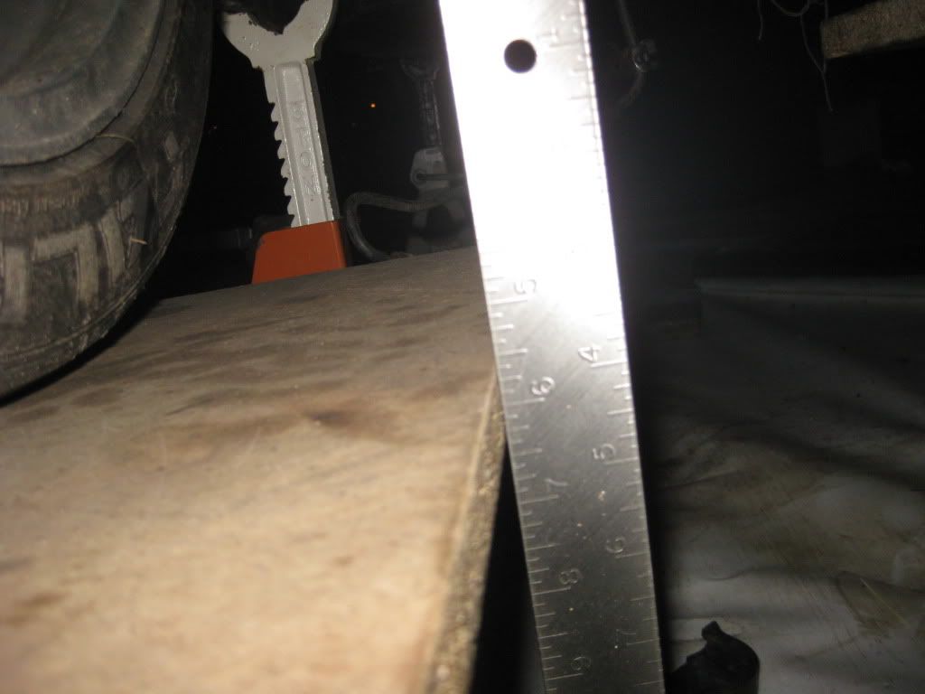
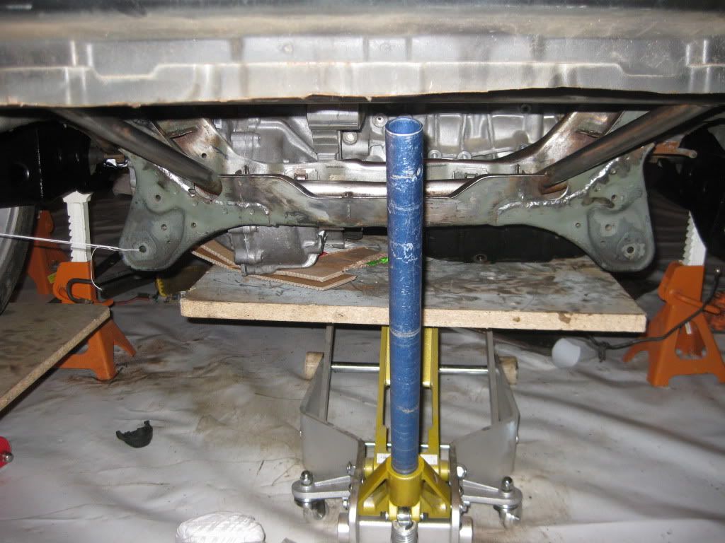
I took some time to figure out ground clearance. A lot of lowered hondas with k20s have around 3.5 to 4" of ground clearance. My estimate right now is that I’ll have between 4-5.5"

my creative way to figure it out:

5.5" from the motor’s platform to the wheel’s
The hein would have to do both. The rod angle with change under compression. And I don’t know what you plan to run for a spring/ strut pack on the cantilevers but it looksfrom these angles that you have way to much mechanical advantage on the strut side. Maybe a different perspective would help me to see it.
Love checking up on this thread and lurking every once in a while.
Keep up the good work! :ninja
Less lurking, more discussion ![]()
the guys on Locost helped me break down my rod end questions:


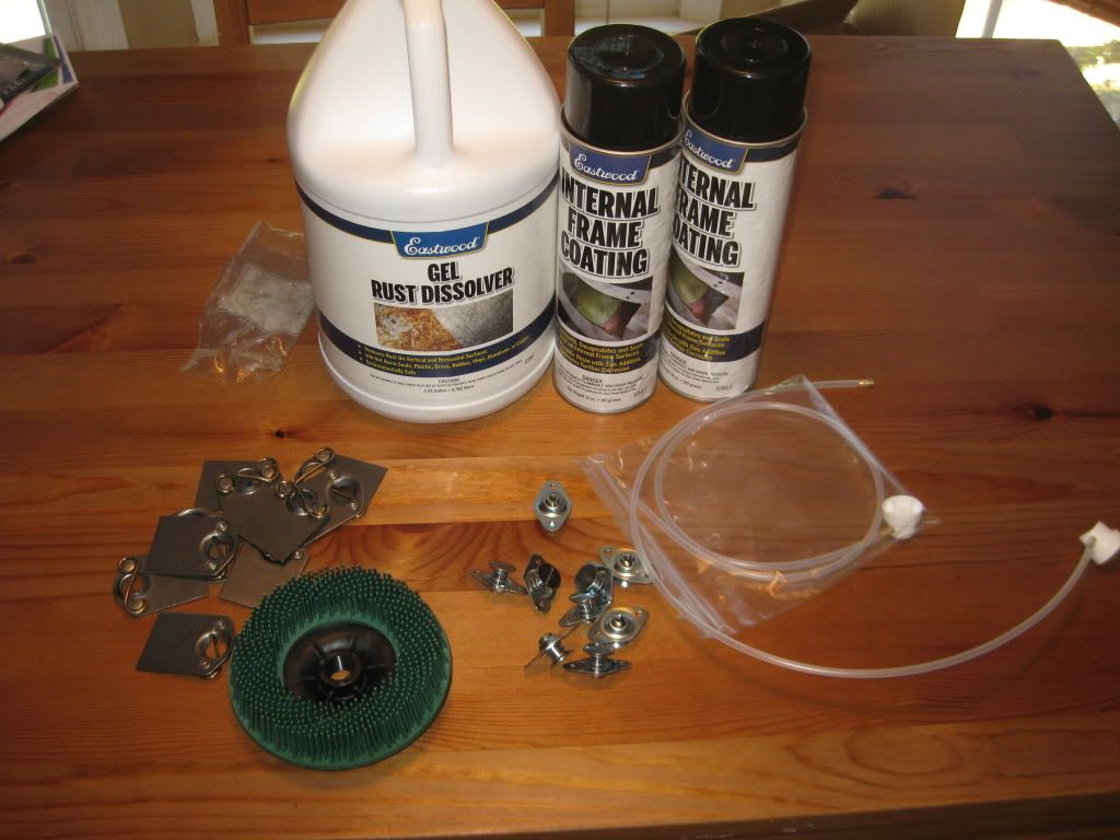
My review of the Eastwood gel rust dissolver:
Con: is not a gel
Pro: quickly dissolves rust
con: causes immediate flash rusting as its removed