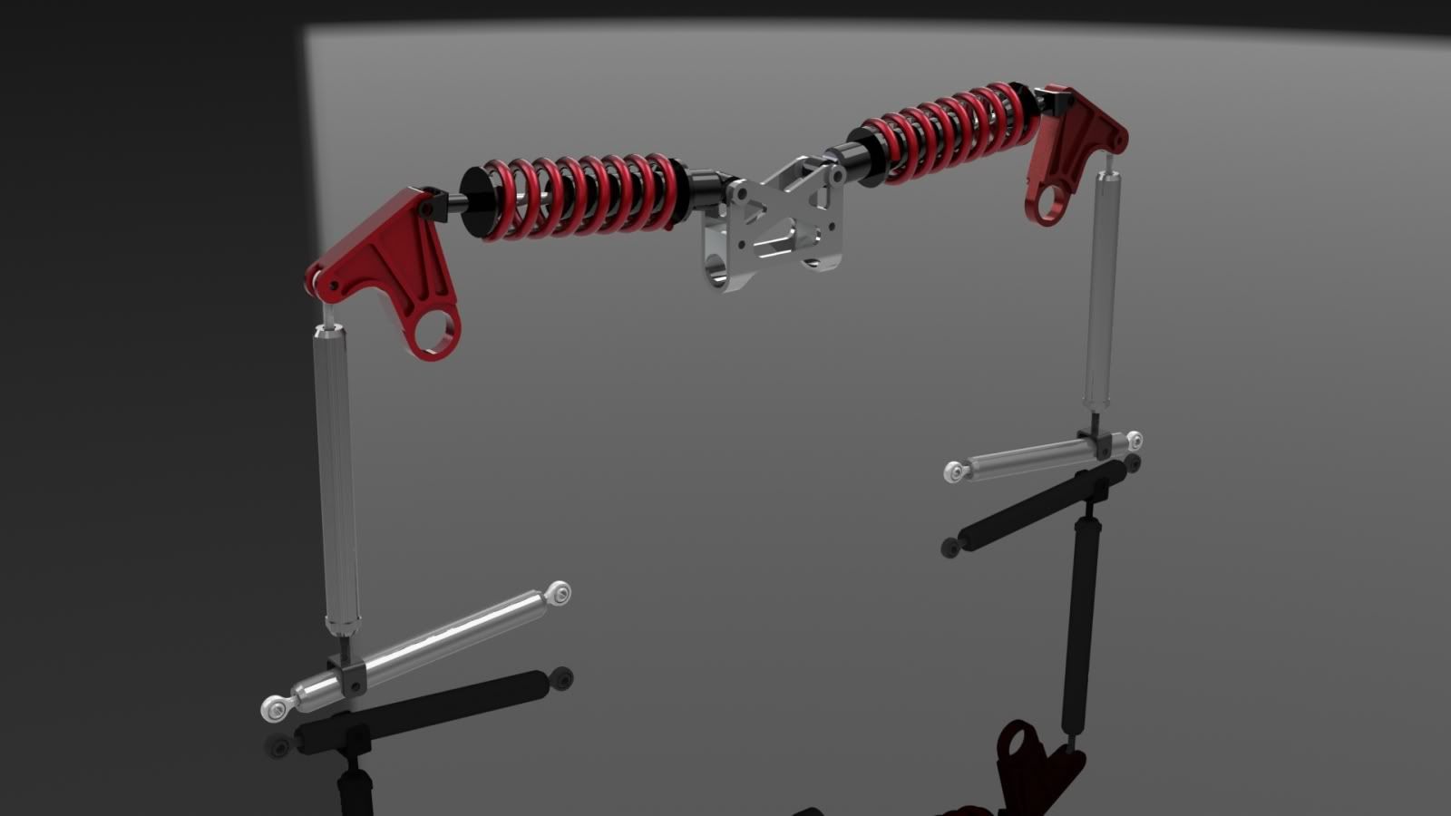
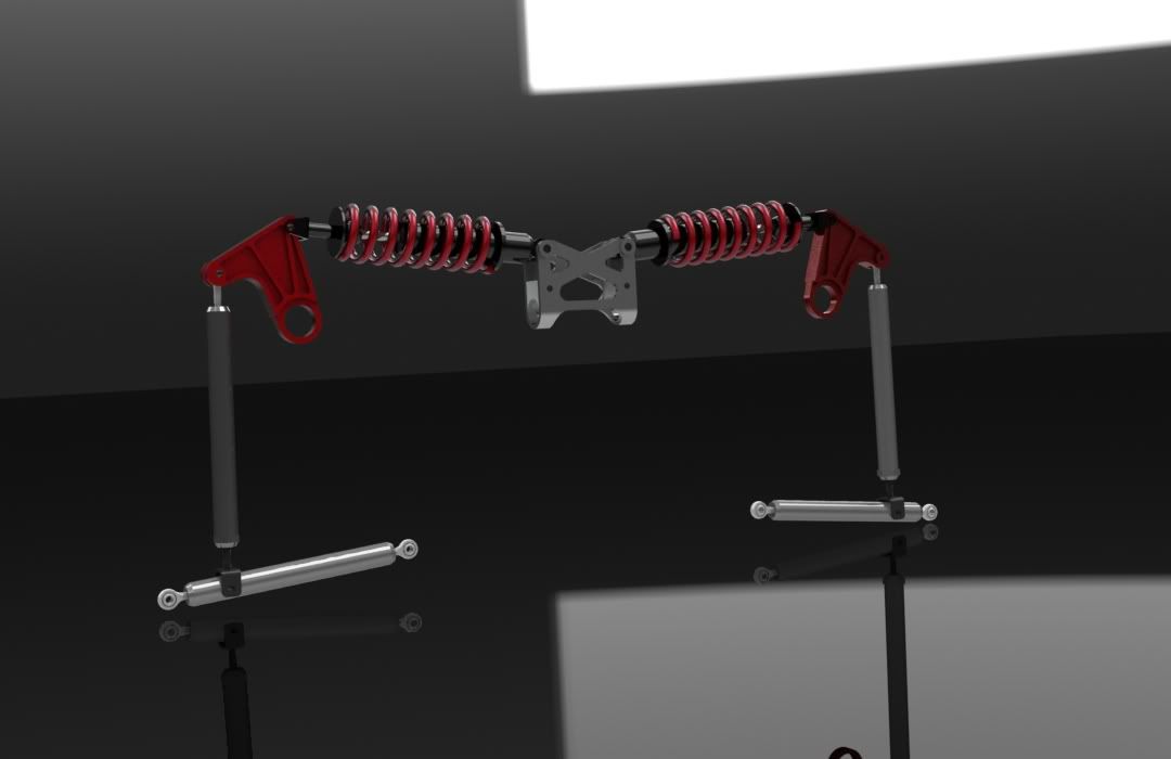
how big? E30’s use something like that for their front swaybar endlinks. Regular non-M E30’s, and its mounted on the control arm.
I need the bracket to be 1.25 wide. I’ve found a bunch of suspension kits that include these as components but I was really hoping to be able to simply order the rod end.
Damn… sad to see that this project won’t be finished yet. Good luck with everything man.
damn, ill have to measure a spare. its gonna be close tho.
edit- that’s 1.25" ID right?
yea, 1.25 ID. I could make larger work. I guess I should find out the size and thread of the rod too.
a few modifications left to make, specifically the center strut mount needs to be redesigned to work with the shock mounts;
definitely make those.
good little project for your new welder 
cool man 
how about running a tube clamp on that lower mid-arm mount kind of like this…

then you would have some adjustment in how much leverage acts on the spring
That’s definitely interesting, I’d be concerned about the strength and it’s ability to be immobilized solely through clamping force. However I assume from that picture that others have tried it before and have been successful.
I had been considering something similar due to my difficulties finding a wide “U-bracket” style rod end. I was looking into a clevis style mount welded onto the arm but the issue I ran into is that the heim rod ends would allow rotation of the lower arm which would produce what would be essentially free movement or “slop” in the suspension travel. The solution would be to mount a clevis/u-bracket on the lower arm bolted through the center of the lower arm OR by putting together two clevis style brackets which would keep the lower arm in line by preventing multiple axis movement (this could potentially creating some wear and binding issues).
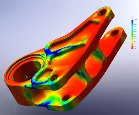
Ideally I will be adding a couple more mounting holes to the bell crank which would allow some adjustment to the wheel rate. Right now I’m struggling with the packaging of it and finding a way to put those holes in the correct location for the ratios I want while preventing collisions between components and while keeping the bell crank strong enough for me to be confident shelling out a little extra money for adam to cnc them for me.
I suppose I always could just do some plasma cut sheet metal bell cranks on the cheap and dirty, but where’s the fun in that?
some motivational pictures i’ve been staring at:

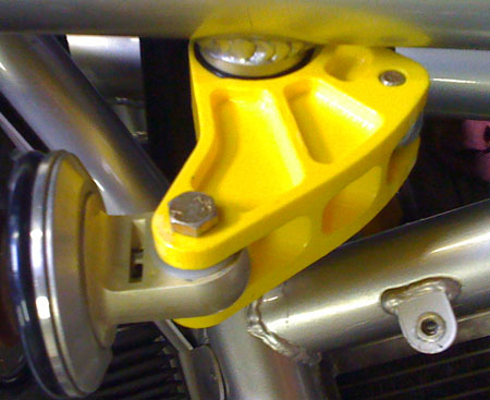
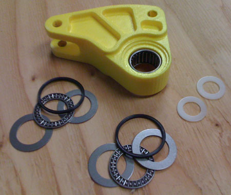
what material is that yellow part made from?
that tube clamp i posted http://www.polyperformance.com/shop/Synergy-Suspension-Outer-Diameter-OD-Tube-Clamp-p-1727.html
is used to attach single ended hydro steering rams to a tie rod in off road rigs. They hold up to turning 40-50" tires in the rocks… so im betting they wouldnt move in your application.
to take the twisting “slop” out of those lower arms, you need to twist one heim all the way left, and the other all the way right before tightening the jam nuts. This allows them to still have the movement you want, but the arm will be unable to twist because its wedged in there.
kind of like this…

but in that pic (shows TREs, not heims… but the same theory) imagine the bodys of the joints out of alignment, and the bolts are lined up.
follow me? or did i make a mess of that explanation? :lol
I can try to get a pic of my tie rod if you want, i have a hydro assist ram attached to it which was making it flop around until i maxed out the heims like i said
yellow part is a rapid prototype part, probably nylon from a SLS- selective laser sintering process. Awesome stuff, and I found a website a while back from a company that will make it and send you the part on the cheap.
as far as the slop in the arm, that does make sense about twisting it, but wouldn’t it cause binding to have the joint maxed out?
also curious how much those tube clamps weigh.
it can cause binding, but from what i understand from your design… not in the plane yours are using.
the tube clamp i linked to is listed as 3 lbs, not sure what size they refer to for that weight.
There are definitely other methods to mount it and have adjustability, perhaps a spine welded to the arm with multiple holes drilled in it, with a clevis mount like you said to attach to the pushrod?
hell, im not even sure if you have the clearances for multiple mounting positions…
What does the complete suspension look like? So I can understand where the twisting can even come from.
Also on the lower mounting point, instead of the thread in U shaped piece, why not just cut 2 triangle shaped tabs and weld them to to top of the DOM tube, as in double sheer and keep both rod ends on the vertical arm? That could also give you a little extra height if needed (as in the controll arm we made was too short).
I didn’t think that would work but now that I’ve played with it in the model I think it might be better.
this is what it would look like stock, but on mine the trailing arm side mount is pulled to the rear about 1.5"
alright, peace out people. Should be back for the month of september.
FFFFFFFFFFFFFFUUUUUUUUUUUUUUUUUUUUUU
Oh word. Well later. Be safe.
thank you so much for your service and I hope you and everone else deployed comes home safely.
thanks, I ended up getting a 72 hour pass to refit and repack. School starts Sunday but I just picked up a nasty virus and I think my training will be cut very short if I show up looking like I do right now.
Might mean more time and less money for the car.
