The diode scheme should work fine. You could use the relay scheme also but I’d avoid the added complexity plus you have make sure the relay coil has a diode across it to shunt the 70+v voltage spike that happens when the relay coil becomes de energized
Couldn’t sleep, so I fell into some white papers on anodizing. I’ve already ordered a handful of anodizing dye packets, so I just need to get some large pots to heat the dye solution and pore sealing bath.
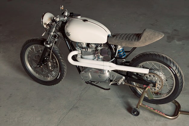
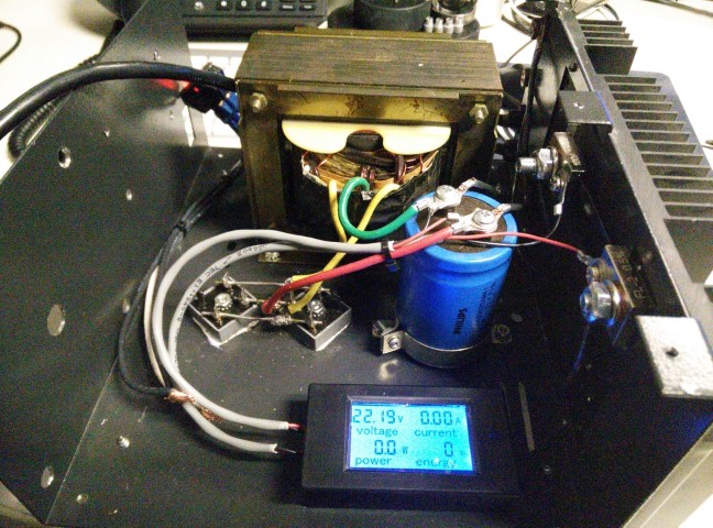
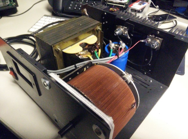
The recommended [DC] power supply seems to be a sort or “whatever you’ve got lying around” type of thing, so I improvised. I found an ~18VAC/~1000VA EI-core transformer in my basement, along with a bridge rectifier array and a relatively gigantic 100,000uF filter capacitor, so I managed to assemble a complete 24VDC/~40A unregulated power supply. I’ve ordered a small LCD-based Voltmeter/Ammeter to put in the chassis and I’ll run it off of a Variac, so I can dial the voltage/current in nice. Should anodize very nicely.
Thinking about going to grab a blasting cabinet today so I can clean up some of these parts to be powdercoated. I’d like to start practicing with that as soon as all of the powder I ordered shows up.
I’ve got access to a 6x6x3 oven I helped build if you want to do your frame sometime. Save you building an oven just for your frame right now.
Oh, that’s perfect! Thanks! I really want to powdercoat the frame, but I’m trying to save building my own large oven until I’ve got my own shop. Definitely running out of room over at pop’s place.
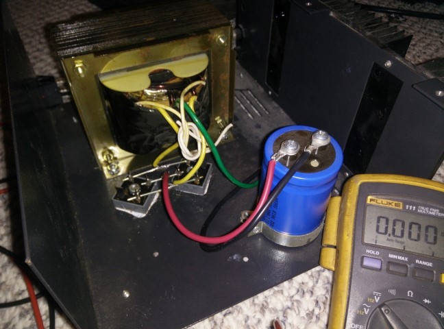
I kept working on that power supply. I bought a chassis-mount W5 Variac, so I can have an entirely self contained, fully adjustable anodizing supply. I’m waiting for that and my LCD voltmeter/ammeter to show up and I can wire all of that in and test it. I ordered and received three dyes from Anodize World aka Toronto Cycles. I bought Fast Blue 2LWN, Green AEN and of course; a bunch of Gold S. I’ve got some scrap to practice on. I need to get a couple of 3-5gal stock pots.
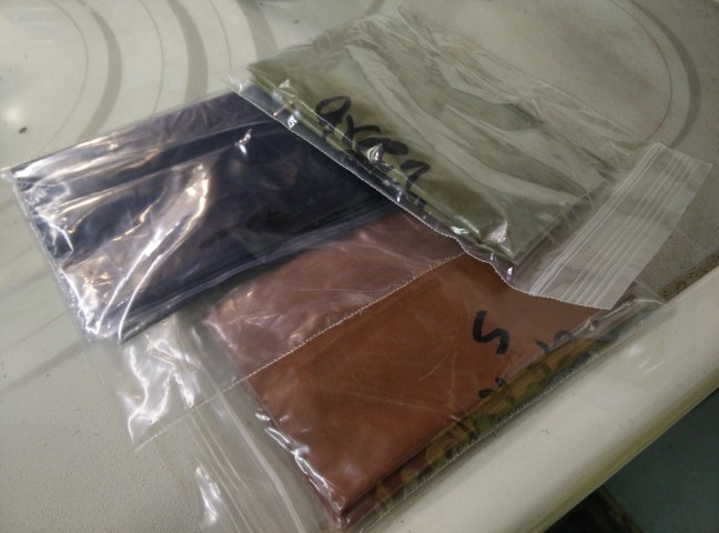
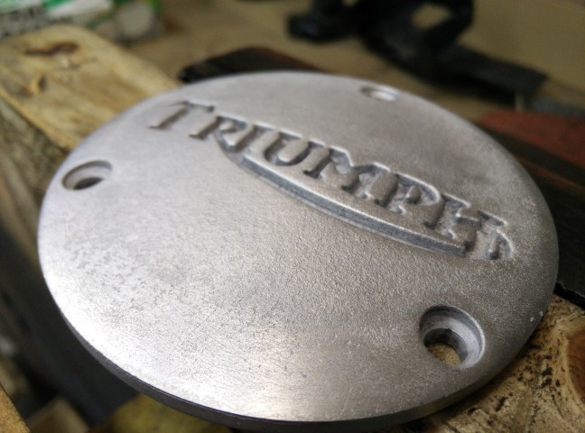
Those parts came back from Tripp.
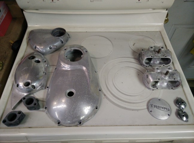
Parts on the left get vapor blasted. Parts on the right get lightly polished and anodized gold.
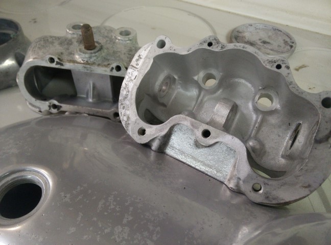
Light oxidization. I’ll probably just scrub these before shipping to straight to Nils.
I’m pretty happy with them. The smaller parts were coated in something, but it polished right off.
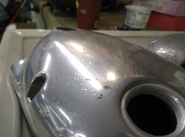
Second picture also shows the choke cable holes freshly tapped 1/16NPT for plugs. Fuck a choke.
Get pitted, brah:
I wonder if it’ll anodize okay with all of those nucleation sites. I kinda like the surface ‘finish’.
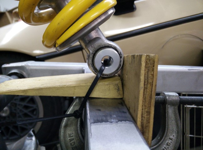
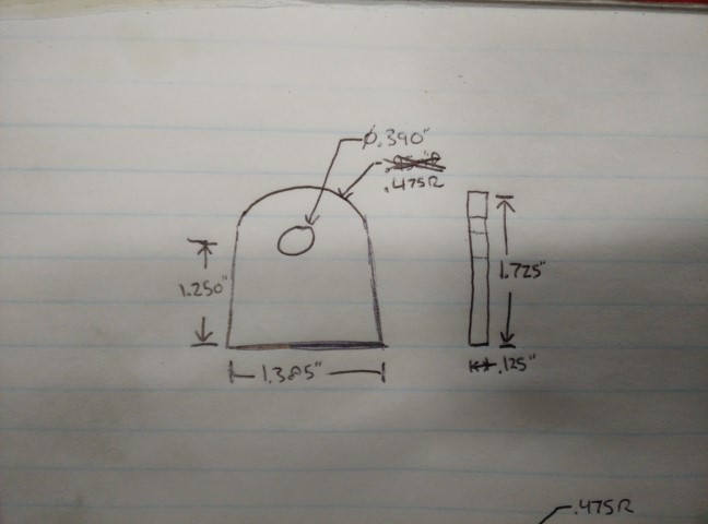
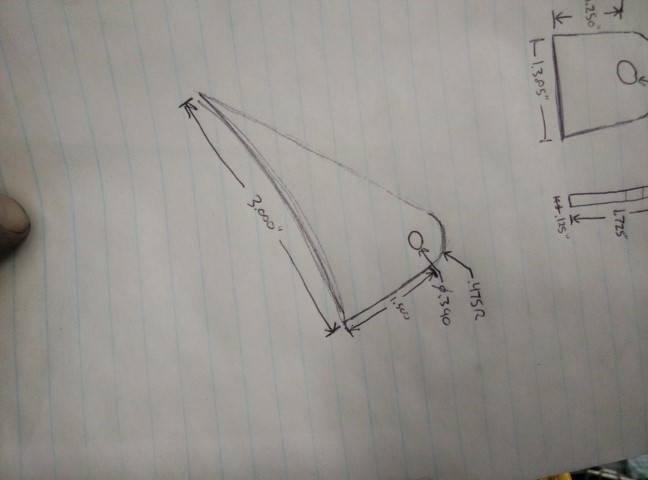
Then I did a bunch of measuring and mocking up for the rear suspension. Sketched some mounting tabs.
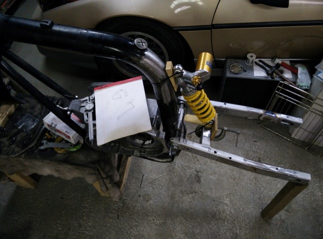
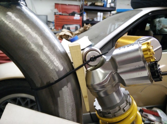
Gorgeous Ohlins.
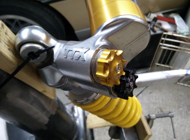
I’ll powdercoat the spring black.
Where did you source the shock from? I was looking to get a set for my CB. Seeing if someone I know knows someone first, haha.
Hah. Where else? eBay. I did some research for shocks that could fit and stumbled upon the Triumph Daytona. Found this Öhlins TTX shock and bought it.
I ordered copper thrust bearings for the swingarm pivot, so next time I’m over there I can make bearing cups and weld them in.
I moved the Dalton down below so I can replace it with a benchtop blasting cabinet.
Lotta ballast down there.
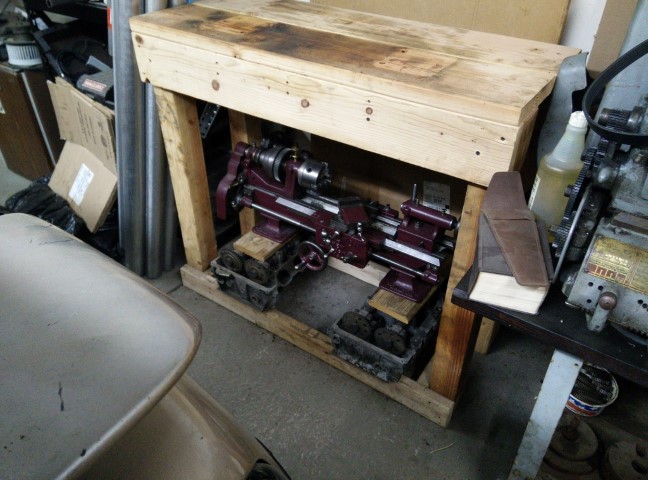
Please cover that lathe before putting an abrasive blaster above it. 
I actually did find a new set on eBay that are from a different model but should fit. Tempting.
I have a moving blanket at home I need to bring back and wrap it with. This lathe will probably never go back into service. It’s really just too small and clapped out. I’m going to put it under a sheet of glass in my living room. Better than an engine block coffee table, anyway.
So when are you calling K&R to come tow the Fiero to the junkyard?
Maybe when it’s, like, wrapped around a tree or something. Not sure why, but I really love that car. …and at this point all it really needs is a motor and some finishing touches. Like I said, I’ll finish up the Triumph and then get back to work on that. Wouldn’t mind driving it around a bit this summer.
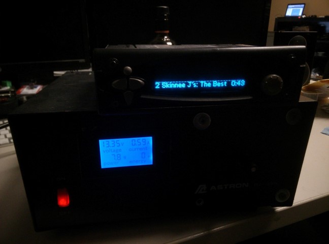
So, that Variac and meter both showed up. Meter is pretty cool. I temp wired it up to test it, but I’ll cut the slot in the face to mount it later. It’s even got high AND low voltage alarms where the screen flashes.
The Variac is another story. I don’t know what you know about transformers, but they typically don’t fail. Based on the following picture, I bought this item on eBay for $40. Not an unreasonable price for a 6-amp Variac.
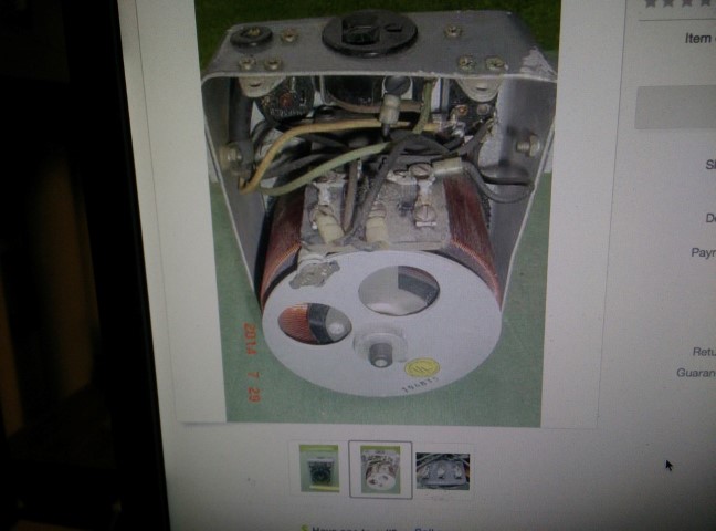
This is what I see when I get it.
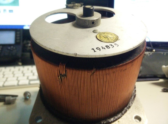
Very obvious damage to the transformer coil, which is clearly exposed and visible to any human willing to open their eyes. This damage, clearly, was not photographed in the listing. You can see from the vantage points of the photos that this damage was NOT hidden, it was openly visible on the bottom of the unit. The listing was ‘For Parts or Not Working’, but based on the photographic evidence, I had no reason to suspect the Variac was trash. $40 for a used Variac is fine. $40 for a piece of scrap metal, some wires and switches is not. This person literally listed garbage on eBay and I was tricked into buying it. I’m fucking furious.
I win.
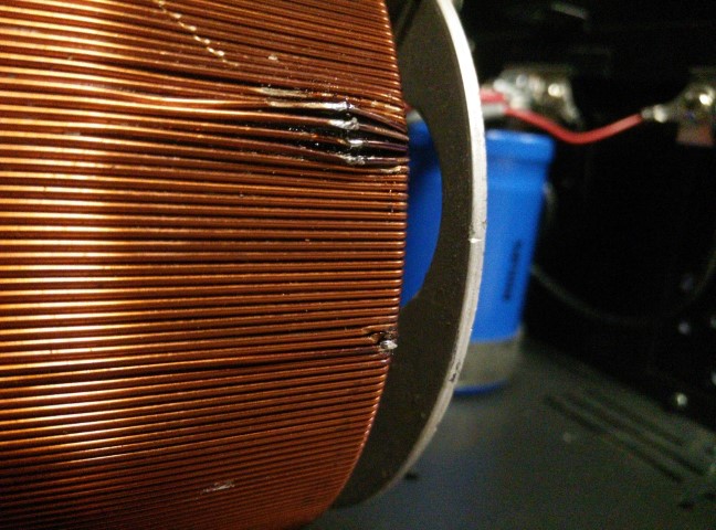
It works. The brush catches a bit when it travels over the repaired spots, but it’s not bad. Should be much easier to turn the Variac once I make a knob on the lathe and install that. If it’s really an issue, I could theoretically remove the dial on the back of the Variac and sand down the rough spots.
This thing is fucking cool.
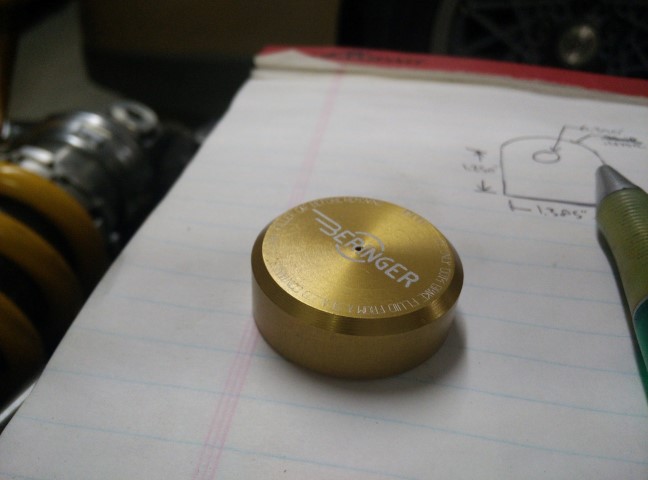
I ordered a Beringer reservoir cap in gold so that I can have a reference for matching my anodize. I’m glad I did. I like it, but it’s not what I expected. It does match the reservoir cap of the Öhlins, which is nice. Not the reservoir body, but the cap. Can’t wait to order the rest of the Beringer stuffs.
I ran down to Metal Supermarkets and grabbed some 1.5" round hot rolled stock so I can make bearing cups for the swingarm.
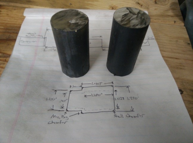
After a bunch of measuring, I started making said cups.
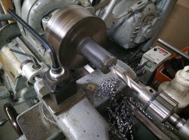
…and about an hour into machining realized that I was about .010" off and my first cup was no longer a press fit on the bearing. Bummer. Guess I get to try again later this week. Ran out of time tonight. I’ll be more careful next time.
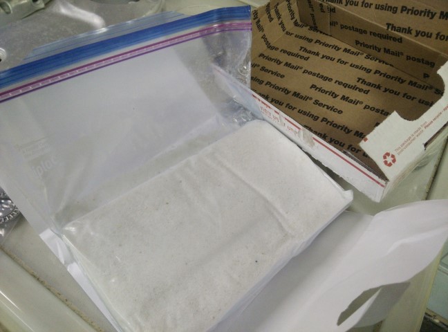
Also got a pretty sketchy looking package. Hah.
Hanging that stock way off the chuck isn’t doing you any favors.
Maybe I’m telling you something you already know, but those cylindrical roller bearings need to be a very accurate fit, and the press isn’t determined by the OD of the cage, it’s actually based off of the OD of the shaft going inside the bearing. If you mic the OD of the cage you might see +/- .001. Are these being welded to something? If not, you should use a better steel that will machine nicer.
That’s ~2.5" sticking out of the chuck. Not sure what else I’m supposed to do with it? The chuck doesn’t even pass 1" stock. This isn’t a 13" Monarch. This is just a little South Bend 9". The entire length of the cup is 2". I’m open to suggestions.
No, I didn’t know that about the cylindrical bearings. That is good to know. I’ll bet that info in in my Machinery’s Handbook. I’ll read up on that.
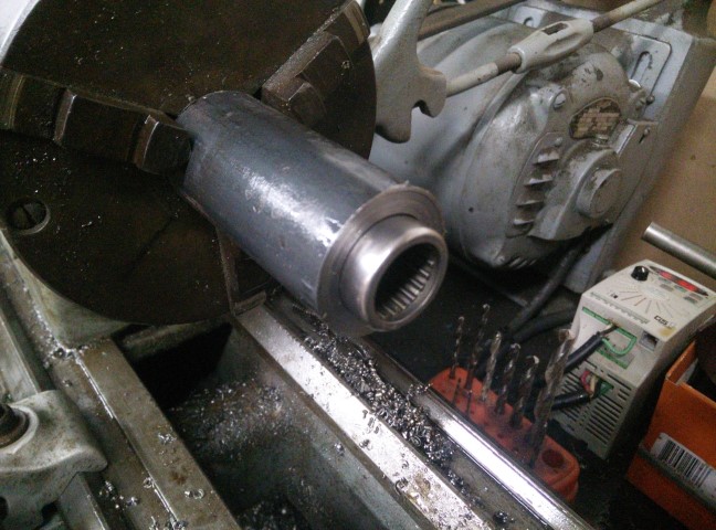
These cups are getting a light press fit into the pre-existing pivot housing in the frame and welded around the seam. I plan on ‘pulling’ the cups into place with a screw-type press and custom bushings to help keep everything aligned.
What gets the fit on the OD? the 1.110 or the 1.370? I’m guessing that the swingarm is narrow and these spacers are making it wider, essentially?
The “right” way to do it is to weld the extensions on and then line bore, but neither of us have the tooling for that. I understand why you want to weld though, otherwise your bearing is cantelevered out in space.
Without changing your direction too much, could you weld the extensions off the frame and then put the bearing in its original place in the swingarm? That would be MUCH easier to fab, because you could put each spacer on the swingarm bolt with a third spacer (equal to swingarm width) between them and then just weld around the outer edge where the two meet the frame. Then you don’t have to fuck around with the swingarm at all, besides maybe changing the bearing. Would be a lot easier to turn a reducer shim than that big long extension.
There really isn’t anything you can do with the material hanging off. What are you doing the ID work with? Boring bar? You could always ream to final.
-
-
- Updated - - -
-
-
-
- Updated - - -
-
Wait, scratch that, I just looked at how the frame is. I was thinking harley/honda swingarms. Looks like the bearings are in the frame and the the swingarm bolt actually rotates with the swingarm?
I assume this is what you are trying to do:

The 1.110" is the OD fit into the frame. It’s the pivot housing attached to the frame that’s narrow. The Ducati swingarm is at least an inch and a half wider at the front than the Triumph one, so I was making these cups to ‘extend’ the pivot housing as well as house the bearings. I was always under the impression that I’d want these type of bearings as far outboard as I can get them [ideally] to reduce the moment about them.
Of course, I’d love to put everything together and line bore it; then I’d have no worries about anything. But you’re right, I definitely do not have the tooling for that. The best I can do is clamp everything nice and tight with good tight fitting bushings and take my time welding to prevent warping.
You mean put the bearing inside of the factory pivot housing? Yea, I could do that. The real problem here is that the Triumph didn’t even use bearings. The pivot point was comprised of ~1" greased bronze bushings that were clamped tight against the frame, and the front of the swingarm just swung around those. Right now, I just have about 3.5" of ~1.1" ID tubing welded horizontally across the frame to work with. Pretty much a blank canvas.
Aah, as far as cutting with any accuracy you’re saying. Got it. Yes, a boring bar. I do have a four jaw for this machine. I suppose I could turn the rough dimensions and then get the piece deep into the chuck for final sizing after centering in the four jaw. Or I could ream. That would be better, assuming it’s a standard size. Not tryin’ to have custom reams made.
Now that you mention the bearing clearances, I should have known better. A few weeks ago I went through CN vs C2 clearances for crank bearings in the motor for this so I should have been prepared to actually calculate the OD for a proper press fit. I suppose I need to look at the bearing and see if it specifies clearance.
Thanks for your help on this.
-
-
- Updated - - -
-
Accurate.
-
-
- Updated - - -
-
OLD WAY:
Swingarm pivot bolt clamps large ~1" bronze bushings against frame, swingarm pivots on those. Bolt and bushings are static.
NEW WAY:
Swingarm bolt clamps to swingarm, pivots inside of cylindrical needle bearings. Needle bearing outer race is static.
It would take some fixturing but what if you just cut off the existing mount and made a new complete one instead of trying to join these three pieces. Moving the bearings outboard is definitely a good thing, though, I understand why you want to do that.
Is the swingarm bolt for the ducati swingarm smaller, larger or the same size as stock?
Lastly, have you considered building your own swingarm? I think you’re capable. It’s not like the ducati one is a thing of beauty, and it is fairly simple.
In this pic you posted, the only thing that sticks out to me as “ugly” is that square swingarm. Looks like something someone welded up in their garage. A round tube swingarm would look a million times better, and you could make it narrower in the front, which would have a MUCH cleaner look. I suspect the other side looks kind of goofy with the swingarm pivot pushed way out further than it needs to be. Then you could tuck your controls in tighter. I digress.