MR2 3S-GTE ECU Repair.

MISTERTWOSINISTER asked me to help him with his 3S-GTE Turbo swap into a 5SFE NA car this past week. Essentially we had to rewire the 3S-GTE ECU Plug “A” to work with the NA body harness. It’s seven wires, no big deal.

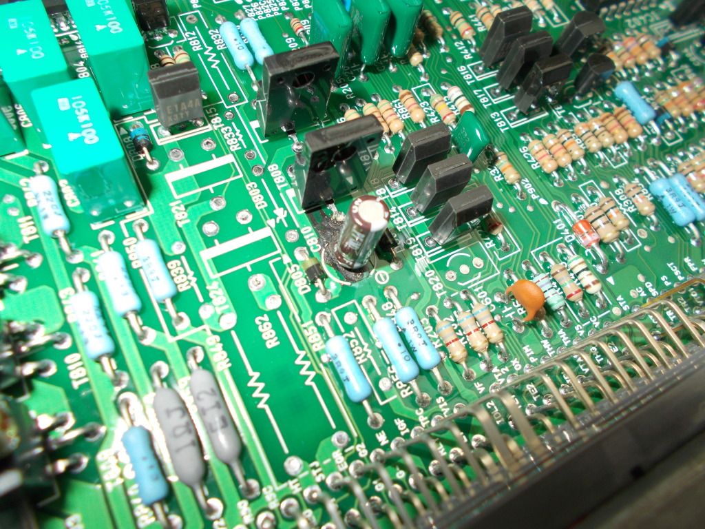
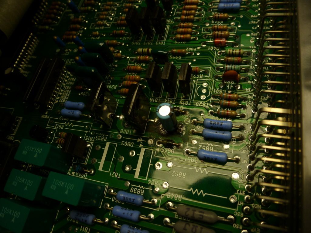
But, after the ECU was wired in it would not throw a check engine light during start-up. After double checking the wiring before did it, triple checked it after we had no Check Engine light, and making a few calls to Waide (an MR2 swap guru in Canada), I was still pretty confident we had a bad ECU. So I opened it up and discovered that components C810 was bad:

As well as C512:

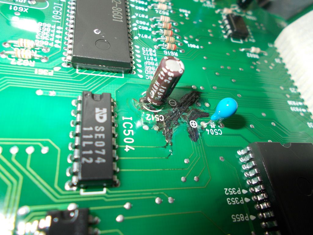
This condition is known as “Capacitor plague.” Over time the capacitor literally “cooks” which leads to leaking electrolyte. I have dealt with this kind of thing before and some may recall I did this repair on sobo’s cluster. This is NOT a result of bad splicing or mixing up wiring…because this simply was not the case.

I removed the bad parts to reveal the affected areas. You can see the traces around C512 are corroded as well.

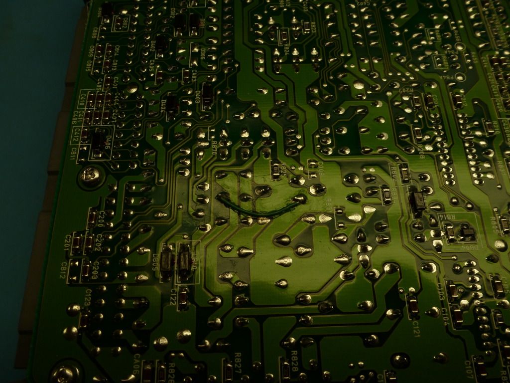
I removed some of the solder resist (Top green layer over the copper traces) so I could perform a continuity check to verify the connections are still good. Well, they were not. There were 6 traces corroded away that need to be fixed as well as the ground plane was no longer connected.

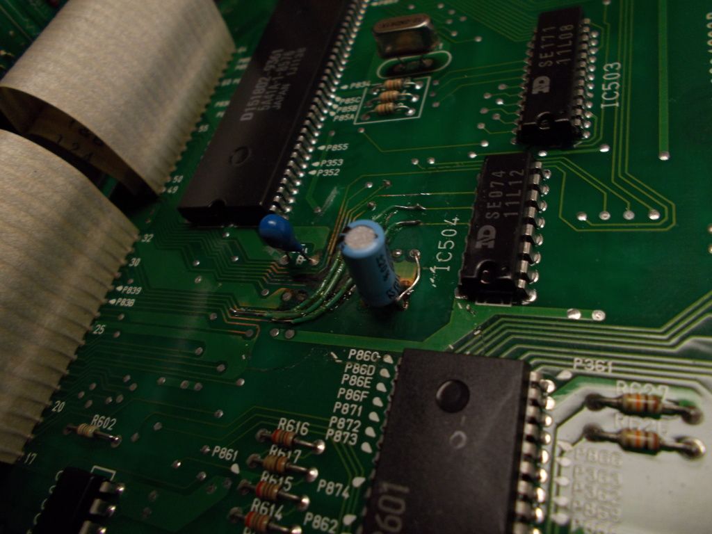
I replaced the Cap with a new 10uF 35 V one. Due to time constraints I opted for whatever Radio Shack had. It would be a good idea to replace ALL the caps with Tantalum caps which can be purchased here: DigiKey Corp.

The jumpers are a 24 AWG heat seal wire. Essentially the wire is coated with hot glue. You apply heat to the wire insulation and it literally glues the wire in place.
Rather than run traces on the back side I was able to figure out where the broken traces where suppose to go. So I went point-to-point. It is much easier to solder in place this way.

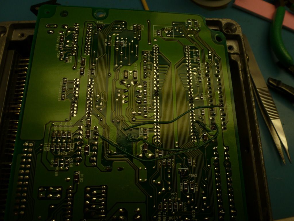
I then moved to C810. There is also something funky here. The difference with this trace is that it is an “Inner layer” meaning the copper traces is insider the PCB. This is common on multi-layer PCBs. Here you can see the trace “Popped” like a fuse.

I replaced the cap and again ran a jumper to the appropriate location.

Once everything was back together we installed it and everything was back to working properly.


So, anyone else having issue with a swap, potentially not throwing the check engine light at ACC, crack open that ECU and look for some blackness.

Another 2 thumbs up to the best electrical guru on this site…

MacGyver Luke to the rescue!

Cool stuff again :tup:

Absurd. Any time I see black on a circuit board I trash the whole thing. I get frustrated just thinking about trying to solder shit that small. But I suppose if you get the right tools and suffer through enough trial and error it’s just another skill set.

Thanks guys!

You make a good point. This was more a “We can’t get another Gen 2 JDM 3S-GTE ECU anytime soon…If we can find one. Plus, it costs $300+” So being able to fix it was the easier solution. Also, you make another good point as a “skill set.” I have acquired this skill through work experience and just adapted it to car electronics. A PCB is a PCB. I’ve repaired Tail Light, Key Fobs, Door Switches, etc… It has been pretty handy and helpful for a bunch of people I have meet on here as well as other forums.

I urge more people to give it a shot. You really can only learn this through trial and error as you stated. It really cannot be taught. It can only be “suggested” on temps and tip size.

Meh I guess you did an okay job.

<3

LOL and I file it squarely under “magic”. That’s why it’s so neat to see you break it down to just another repair job, albeit with its own unique challenges. I.E. I’ve never even heard of that wire that adheres to the board, and have no idea about soldering temps. Post a shot of your tools if you get bored enough. I’m guessing a temp-adjustable soldering iron with tiny tips? How do you cleanly desolder the bad parts? Do you use something to clean off the slag or just blow it off? Magnifying glass? Wrist rest? Decaf coffee? Do you use some kind of jig to hold the board? Are you actually a tiny elf?

lol

I have a Weller WESD51 (Digital) but you can get a non-digital for $100: http://www.parts-express.com/pe/showdetl.cfm?Partnumber=372-145

For tools, you need a good pair of precision tweezers, precision cutters, and some times sturdy needle nose. I suggest Techi-Tool for those.

Solder flows at 363°F and become liquidus. Generally speaking, you never want your tip touch time to be more than 2-3 seconds. To achieve this you need a much higher tip temperature than the flow temperature.

For small terminations I set my iron to 600-650°F and use a 1/8" tip. Smaller fine pitch parts I use a smaller tip.

For larger parts and pads with large heat sinks, ie grounding plans with alot of copper, I set my tip temperature to say 750°F an I may change my tip size to 3/16" if the leads are rather large.

Your tip should never be larger than the pad you are soldering to.

The best way is to use something called Solder-wick. It is woven copper strands that you use to literally soak up the molten solder. Apply flux to the solder, apply flux to the wick, place the wick over the solder you want to remove, place tip on the back of the wick to remove solder, then clean with a solvent to remove flux (IPA or Acetone).

If you do get solder splash it typically will harden and can be blown off. Any flux needs to be removed with a solvent if you use Rosin or water is you use water soluble. I DO NOT recommend water soluble UNLESS you submerge the PCB in water. You cannot locally clean water soluble flux and it is VERY corrosive compared to Rosin flux.

I am near sighted (-5.25) so most work is done without magnification. I typically check connections under a 10x eye loupe or a microscope.

Don’t use one. But I kind of perch my hand with my Pinky or Ring Finger as I solder. Hold a pencil and stick your pinky down straight then use your index finger to move the pencil up and down your middle finger…that’s the technique. If you can do that, you can solder!!!

I don’t drink coffee… I think the last time I tasted coffee was about 6 years ago. My co-worker bought it as a kind gesture for me helping them out with a side project, so I choked it down.

I use a panavise…best invention ever for small work.

LOL…

Very interesting! Thanks for taking the time to explain.

You’ve got more patience than I do. Nice work.

Just to add a few note for anyone wanting to learn -

Solvent for cleaning flux = Isopropyl Alcohol (rubbing alcohol) or Acetone (Nail polish remover)

The solder they sell at HD/Lowes in the plumbing dept… don’t use that for electronics, not only is it not made for it, it’s WAY to large in diameter to be able to control the placement of the solder.

I’ll second that Weller WESD51; that’s the same one I use and it works great for electronics.

Good points, thanks Mike.

The best local place to buy solder for electronics is Radio Shack.

The best place to buy the solvents is either a drug store or a Target/Walmart…unless you wants a half gallon of Acetone from Home Depot. Do not get the dyed (Sometimes Red, Blue, or Green) Nail Polish remover.

The more pure rubbing Alcohol the better, for cleaning. You could get a 80-90% for electronics and put it on your work bench and keep the 70% in your bathroom cabinet.

Nice work…

Once in a while I miss the fun that is was to add jumper wires to microprocessors and “repairing” boards.
2 layer PCBs FTW.

FYI…
Caps are one of the major problems in TV/LCD monitor repair…
$4 in parts has made me look like an evil genius more than once :slight_smile:

I would love to pick up a broken monitor and fix it…any leads?

Yep…
Trash day.

CL ad maybe?
Broken stuff usually finds me and thats OK as I usually work for whiskey/beer

Great work and explanation as always. :tup: