nice project
you can have 8 letters on a plate.
Looking good.
Its nice you have access to those mills and other machines, it really opens the door to custom fabrication.
–mark
how about you trade me your rb for my ka motor so you can expand on your ideas more and continue with more diy stuff
lol awesome project
hanging out with kyle, taking pics of woz sitting on rocks.
obviosuly, we went to TJ last night, i didnt even think it was possible for people to go that dumb.
and yes, were getting alot of good pix. wait till u see this one scrapper we saw downtown, the back end was about 2in off the ground, i dont think he even had to gas brake dip to scrape, he just scraped due to minor changes in the contour of the road
-originalsin
Ok, last night i got back into it, no pictures though, sorry.
We removed the fuel tank and stripped the sound deadening from the interior.
We decided that we are going to run a 10 Gallon-ish fuel cell in the spare tire well, with the sump mounted such that it hangs out of the well a bit.
My GT35R arrived, but had the wrong exhaust housing on it, so we sent it back. We also decided we are going to be making a new exhaust manifold. The old one i made was “suckier” than i remembered it being… Plus it gives us a chance to use Don’s new, baller ass header modeling system.
The next step is going to be to mount the engine and transmission, as well as cut out the transmission tunnel. While we are welding in the new tunnel, I want to take care of the few rust holes in the chassis…
I’d really like to have someone knowledgeable with bodywork have a look at it and tell me how this should be addressed
So if you’ve got experience with this kind of thing… especially those people who restore old cars, let me know when you can have a look at it… maybe lend a hand… It’s one of the few things that don and I know very little about.
I hope to have the motor mounting squared away before the following weekend…
I know someone…
we could come sometime tonight or this weekend if you like.
[QUOTE=newman]
The next step is going to be to mount the engine and transmission, as well as cut out the transmission tunnel. While we are welding in the new tunnel, I want to take care of the few rust holes in the chassis…
I’d really like to have someone knowledgeable with bodywork have a look at it and tell me how this should be addressed
So if you’ve got experience with this kind of thing… especially those people who restore old cars, let me know when you can have a look at it.QUOTE]
could prob. help you there…any pics for starters?
OK.
Back in the shop today.the next step is mounting the engine and transmission. Since the transmission tunnel requires heavy modification to allow the transmission to fit, we are first going to mount the engine, then the transmission.
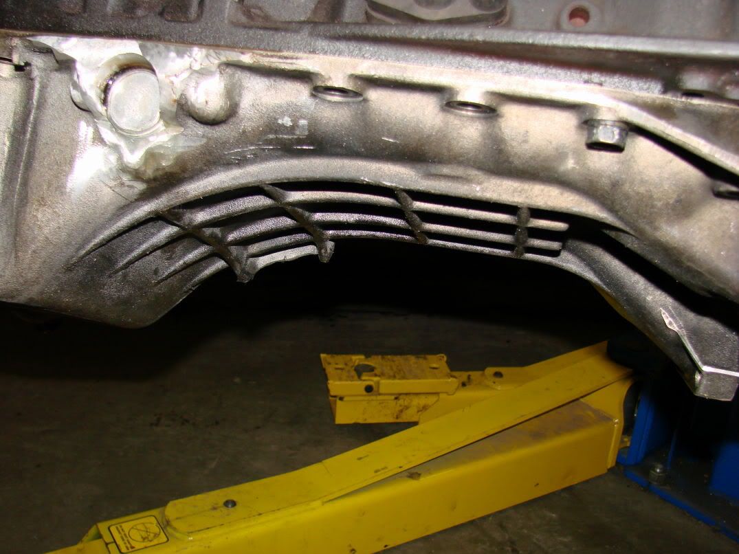
The major constraining body is the oilpan/crossmember interfaceto be safe, I decided that a minumum 3/4" of clearance will suffice. The motor is going to be solid mounted, so this shouldn’t be a problem.
This is the shape of the oilpan:
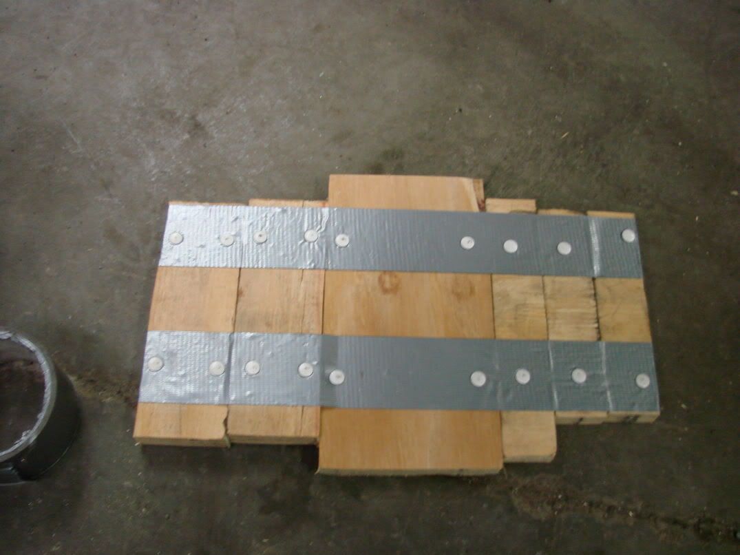
So i crafted up this shim out of 3/4" plywood:
Then installed it with some mechanic’s wire. (OK, I lied, I couldn’t find any mechanic’s wire, so I just jogged some welding wire out of the mig):
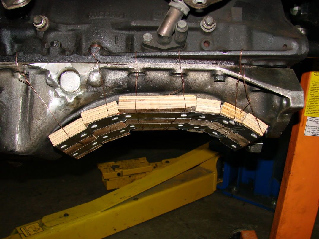
This shim will allow us to set the motor right onto the crossmember, design and build the motor mounts, then the shims will be removed, allowing for the 3/4" of clearance.
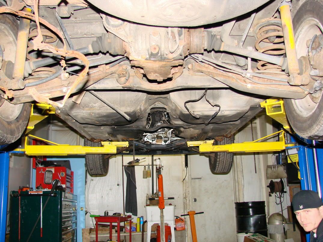
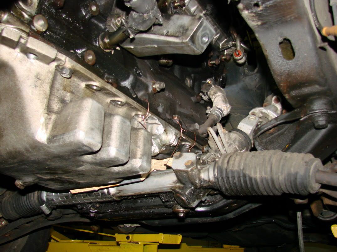
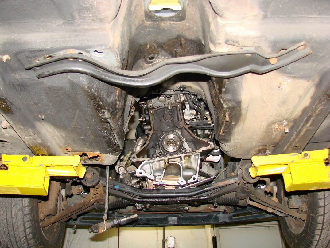
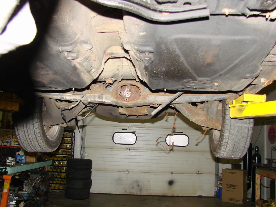
So we set the motor in the car. We used mike’s skyline to get some preliminary measurments and angles. I was really nervous about how the motor would fit, viewed from the rear, but i was quite pleased with the result. Some minor shimming and twisting, and i think we have a very close idea as to a final motor position. We are going to use something like this:

on the flywheel mounting flange to perfectly aim the engine at the rear dif.
Here are some pictures of the motor resting in the chassis (that’s turbociv in the lower right of the first pic):
Nice progress! What time were you guys there? I came by at 10:30 and no one was there 
looking good. good thing you didn’t forget your water pump or anything…
we were there probably no later then 6pm. Don had to go eat some steak in his new classy shirt.![]()
buhahahahahah you know how classy it was…I realized they screened the suspenders for the holsters THEN put the pocket over it so the suspender was covered by the pocket…noobs ![]()
Sunday:
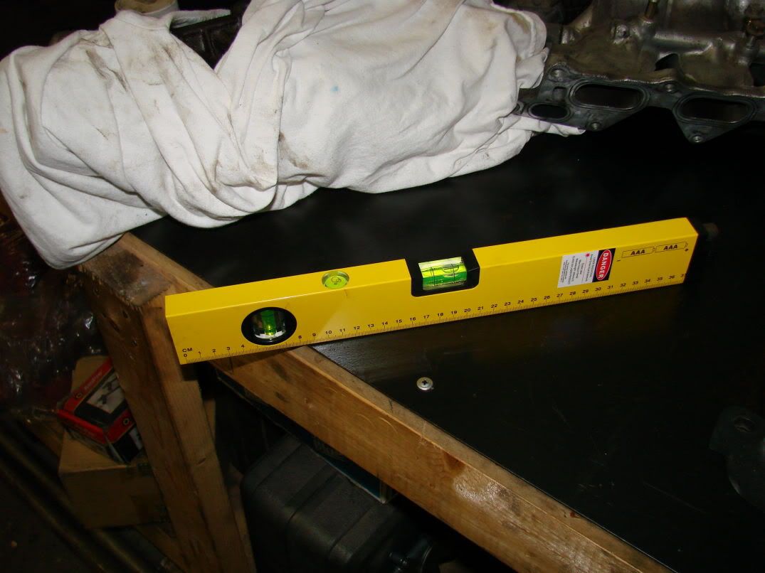
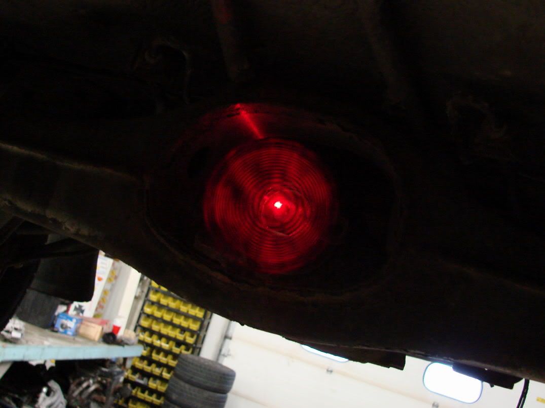
Got that laser level from harbor freight. They didn’t have the 16 dollar one, so i had to buy the one that came with way more bullshit:

It was 40 bucks. Meh, whatever.
So i butted the end up against the crank snout. Like so:
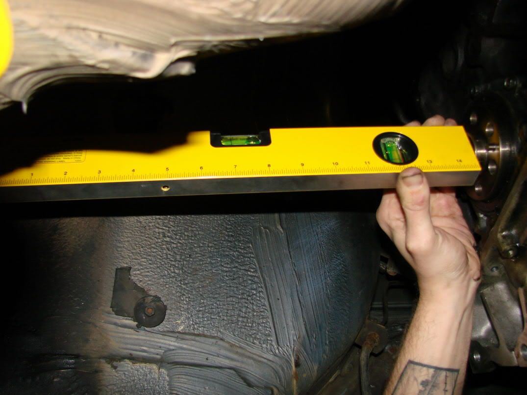
Apparently my “eyecrometer” was right on… If you look carefully you can see the red dot right in the center of the diff flange.
Since i know the motor is more or less in an good position, I started mocking up TEMPORARY motor mounts out of some angle stock i had laying around. I will finish these and post pictures tommorow.
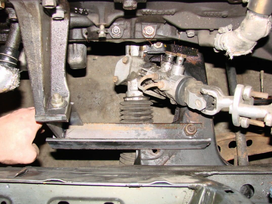
The bolt hole in the lower angle is actually a ball joint on the lower control arm. The actual motor mount bolt is about 3" forward of that. The final finished motor mount will utilize both bolt locations to account for the fact that the motor is creating such a large moment on the crossmember. I may also triangulate the motor mounts forward into the radiator support or simply tie into the “frame rail”. Either option will help stiffen the front end up. Much like the nissan “power brace” does on S13s:

looks good
nice progress newmanator…