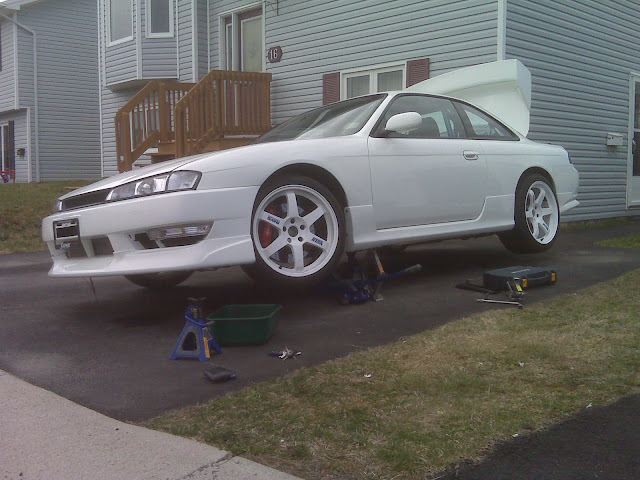
Big update from today, spent about 5 hours total wrenching and made a good bit of progress.
Updates include:
- Tire size and width comparisons between all my tires
- Rear multilink completion & adjustment
- Differential/handbrake cable clearance
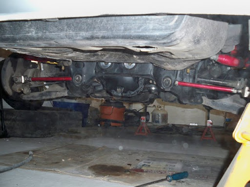
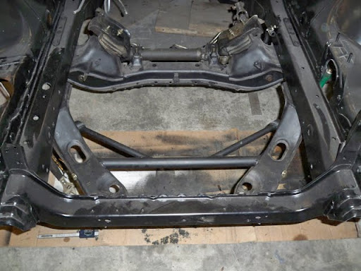
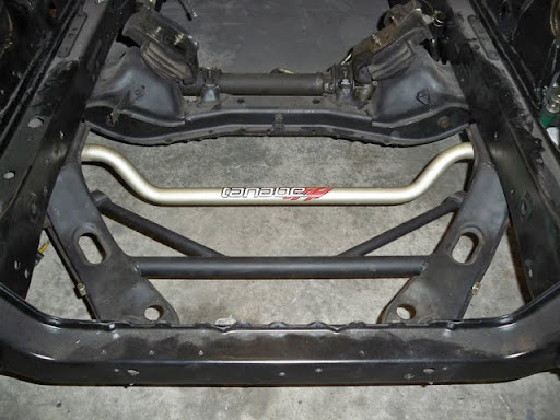
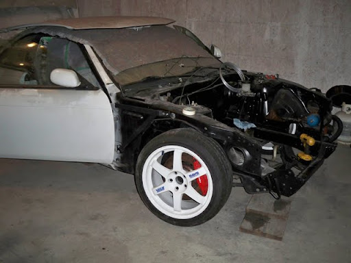
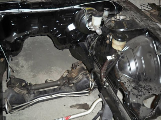
- Rolling Chassis
- Interior Paint
To get started, here is a comparison of all the tires I currently have in the garage.
I had to pull down my wheels in order to get the car back on the ground, and it turns out that my rear wheels were way in the back of my tire shelf. I figured that while I’m pulling those out, I might as well take them all down and get some measurements.
All the wheels/tires down off the shelf.

Then I went out behind the garage to use “the facilities”, and realized I had 4 more back there, lol.

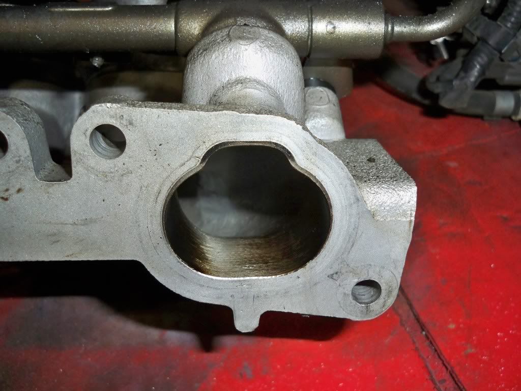
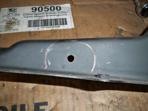
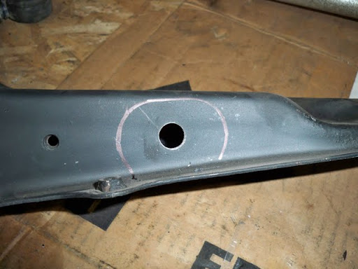
I got a measuring tape out and measured everything; the results are pretty interesting. If you look at your tires, there is a “ring” outline that is molded into the edge of the tread on either side.
You can see the “ring” here, and can also see where the sidewall drops off to start the bead.

I measured the tread width from “ring to ring” across the tire tread.
The sidewall was measured from the top of the bead to the ring.
The overall height was measured from the floor to the top of the tire (by sight), so may not be exactly accurate.
The only things that would make some difference in measurement is:
- The contisports are mounted on 9.5" Volks (Used tires)
- The Summitomo’s are mounted on 8.5" Volks (New tires)
- The BFG R1’s are mounted on 8" Enkei’s (Used tires)
- All other tires are unmounted/new
- I would say that overall height is increased when mounted/inflated.
Here are the results.
W = Treadwidth
H = Overall height
S = Sidewall Height
- I measured these with a tape, and by sight, so they’re more of a benchmark than exact data.
Hankook Ventus R-S2
265/35/18
W = 11 1/8"
H = 24 1/4"
S = 1 3/8"
Continental Contisport Contact 3
255/35/18
W = 10 1/8"
H = 24 5/8"
S = 1 3/4"
Hankook Ventus R-S2
235/40/18
W = 10"
H = 24 3/4"
S = 1 5/8"
Sumitomo HTR Z III
245/40/18
W = 9 1/2"
H = 25 3/8"
S = 2"
BF Goodrich G-force R1
245/40/17
W = 10 3/8"
H = 23 3/4"
S = 2"
350Z Spare (lol)
T125/90/D16
W = 4 1/8"
H = 24 1/8"
S = 3"
The first thing that stood out to me is the difference in width between the 265/35 Hankook’s and the 255/35 Continentals.
-
It “looks” like the Hankook 265’s are an inch wider than the 255 Continentals.
-
If you look at the picture below, you can kind of see that the Hankook tread “wraps” around the sidewall more than the Continentals do, so it may explain some of the difference.
-
The continentals are also worn, so they’d measure a little less than new.
-
However, a 265 vs 255 shouldn’t really be a full inch, so I’d say that R-S2’s are wider than Contisports in general.
-
The difference in overall height may be partially due to the Continentals being mounted and inflated.

Then, when compared side to side, the 255’s look as wide, or wider than the 265’s…but this is mostly due to the slight stretch of the 255’s to fit the 9.5" wheels. They don’t necessarily have more useable tread.

The next thing that stood out to me was the difference between the 235/40 Hankook’s and the 245/40 Sumitomo’s.
You would think by size/spec, that the Sumitomo 245’s would be wider than the Hankook 235’s, but the 235 R-S2’s are actually a half inch wider than the 245 Sumitomo’s!
- I would kind of associate some of this with the Hankook apparent trait of wrapping the tread around the sidewall a little, but given that the sidewall and overall heights are so much greater for the Sumitomo’s, I’d say that the Hankook’s are certainly wider than the Sumitomo’s in general.
- When I say “wider” here, I mean they would have more useable tread, and wouldn’t roll over onto the sidewall as easily - if they began to roll, there would be a little more tread available.

Finally, when looking at the BFG r-comps, it’s very apparent that they’re much wider than a regular 245 spec tire. Both the BFG and the Sumitomo’s are 245/40 (17" and 18" respectively), and both have 2" sidewalls.
However, the BFG tires appear to have a tread width of 10 3/8" (even when fully worn/corded in small sections). When new, I assume these are 10 1/2" or better.
- First of all, here is the 245 BFG vs a 245 Sumitomo…huge difference.
- The second picture shows that not only is the visible section wider for the BFG, but the “ring” is wrapped around the sidewall for the BFG, and almost stretched for the Sumitomo’s.


Also, BFG 245 vs the Continental 255.
- Again, the 255 “seems” wider, but it’s the stretch you’re looking at, not the tread.
- Also…when cross-referencing the pics, the 245 Sumitomo looks way “thinner” than the 255 Continental.

After considering all of this, I think that I’ll be running the R-S2’s on both front and rear this year 265/235 split. Last year I corded my front Continentals the day that I ordered all of the R-S2’s, and couldn’t wait the couple of weeks that it usually takes to receive Tirerack orders, so I bought the Sumitomo’s as more of a “need” for somewhere in the ballpark of 550-500 on sale.
I was thinking about using them with the rear Continentals until the Continentals needed replacement, then doing them all at the same time, but I think I’ll go for the R-S2’s before the season now. Probably throw the others up for sale, as they’re all still new.
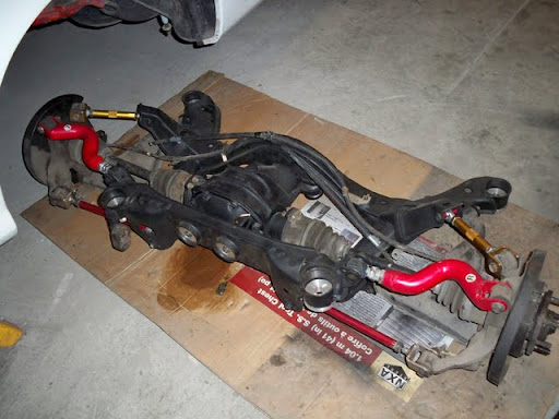
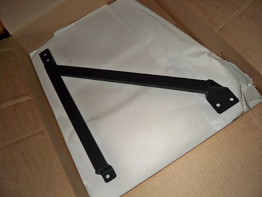
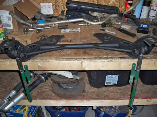
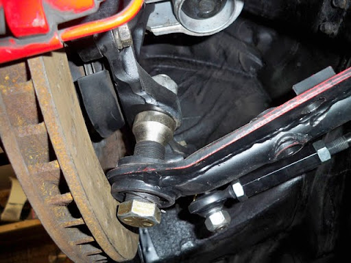
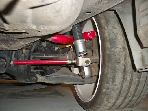
After I put all the extra tires away, I went about adjusting and bolting up my rear multilink.
(Epstein, I hope that you don’t mind me referencing your graph photo. Let me know if you’d like it removed.)
The following description is somewhat of a personal reminder of all I’ve been reading up on these past weeks, so pardon the lengthy facts. 
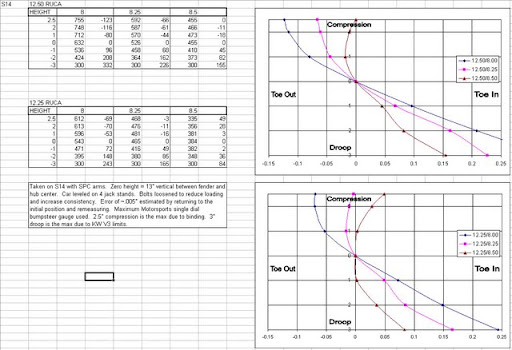
A fellow member of NRR plotted and posted these graph’s for everyone.
They’re plotted for the rear suspension of an S14.
- If you look at them, you can kind of deduce that as RUCA length decreases, the total change in toe across all compression/droop becomes more vertical (less change).
- You can also see that as traction arm length increases, the toe seems to head in the “in” direction across the board as opposed to the “out” direction.
A few quick facts on the 240SX suspension.
-
The front suspension tends to toe out under acceleration/braking/rolling resistance, so factory toe may be set a little “in” to make up for this.
-
The HUGE stock factory tension arm bushing (controls fore/aft movement of the flca) and other front rubber bushings have totally been removed on my car, and all front is now spherical (and braced/bumpsteer adjusted).
-
This greatly decreases the amount of toe out effects with load, so if I run 0 static front toe, it will probably stay close to 0, and a little out under load.
-
A little toe out in the front isn’t bad, as I ran some static this year, and it seemed to help with turn-in.
-
The rear suspension tends to toe IN under acceleration/etc.
-
Toe in helps with power-down out of a corner with the rear multi-link setup, and gives better stability throughout corners, as opposed to the twitchy toe out condition.
-
Running 0 static toe in the rear, and having mostly upgraded/spherical bearings will decrease the amount of toe in throughout compression/droop, and using the specs plotted above, I should see all toe in, and NO toe out. (desirable).
Stock RUCA length is 12"
Stock Tension rod length is 8.25"
When I adjusted my arms today, the RUCA was 12 1/8" and the Traction rod was 8.25".
I increased the Traction rod to 8.5", and left the RUCA at 12 1/8" (for simplicity - err got a little lazy).
I’m a little lower than this guy (Maybe ~0.5" roughly).
So judging by the graph’s (and this is all rough, as each setup is different), I’d say that running 0 static toe will net me close to 0 toe for the first inch or two of droop, and will give me (hopefully) toe in under any compression (turn/acceleration).
Realistically, I won’t have any more than 1.5" of compression, so 0.05" - 0.1" of toe in (or thereabouts) seems acceptable. Judging by what I’ve seen today (next pictures), I’ll actually have about 2.5" (max) droop, so keeping the tire reasonably close to 0 toe is desirable there I would say.
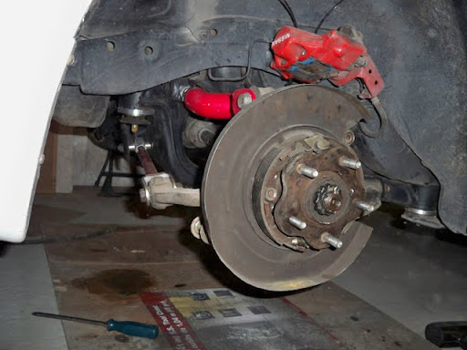
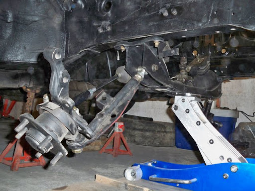
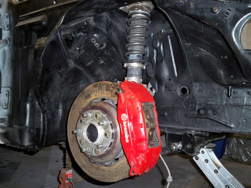
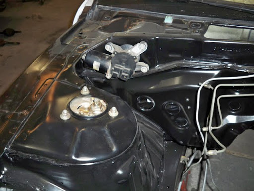
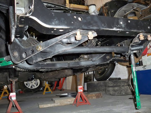
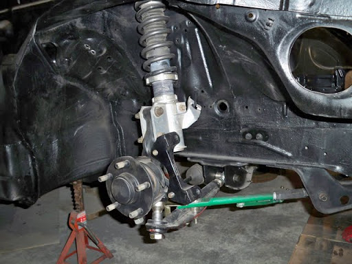
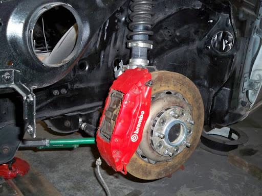
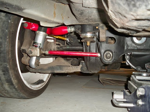
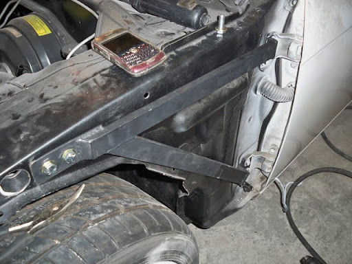
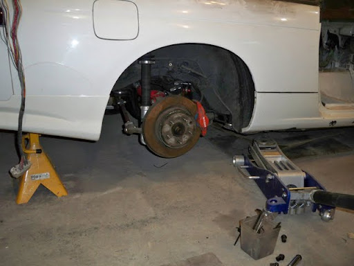
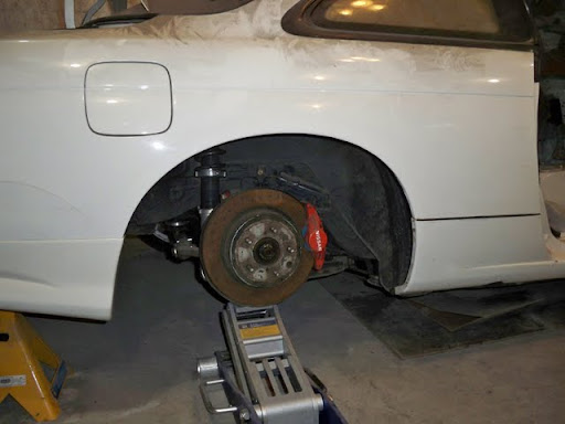
After adjusting everything, I bolted on the coilovers & brakes to measure the new droop, and get the car back on the ground.
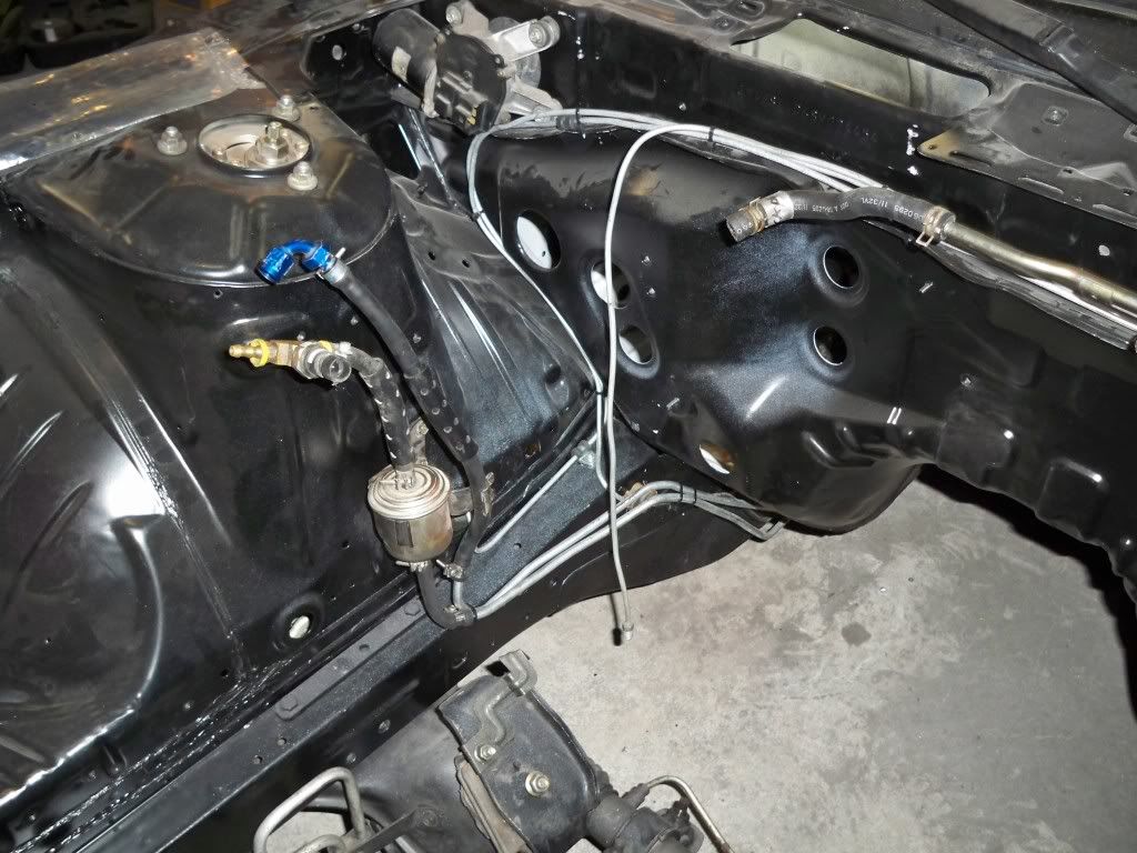
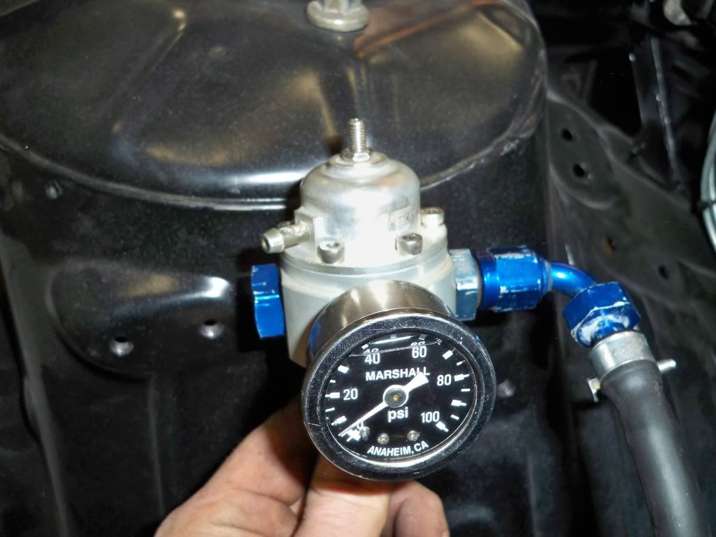
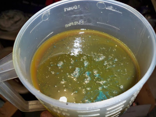
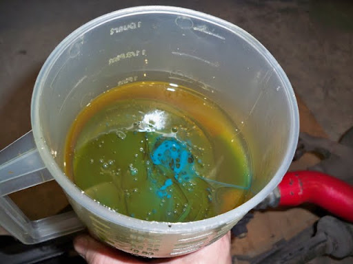
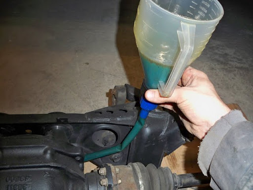
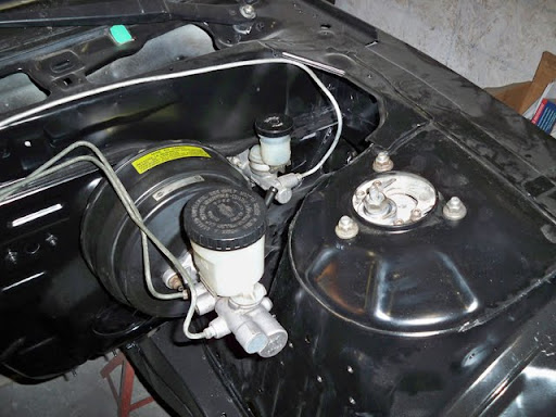
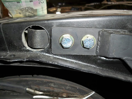
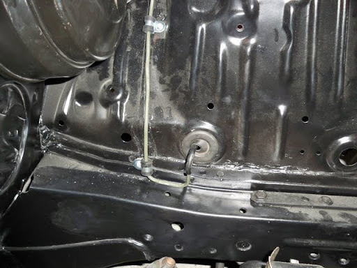
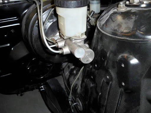
I installed a generic filter on the vent line that I was referring to in the “vent line” thread, then ran it into the rear frame rail where it will remain dry, and have “clean” air available through the filter. i.e. the inlet action won’t have crap or water in it, and the outlet will just be into the frame rail.


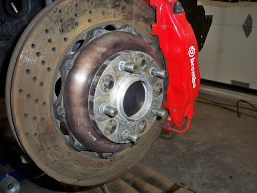
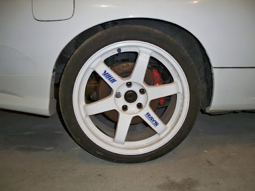
Coilovers & brakes.

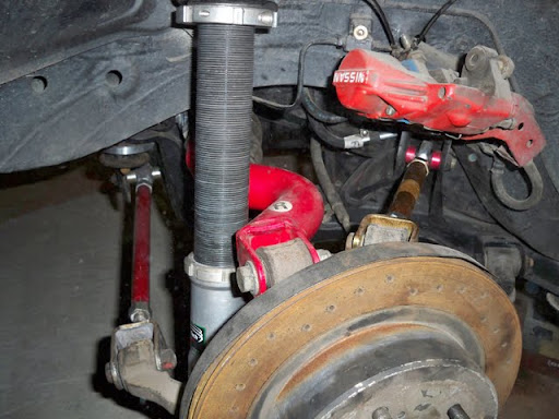
Calipers

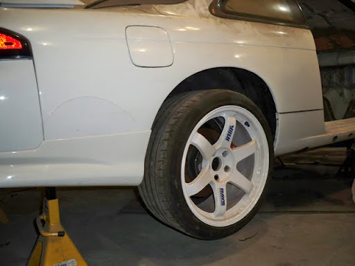
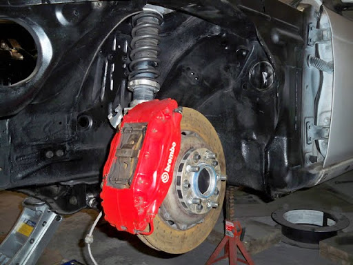
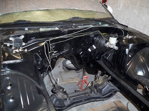
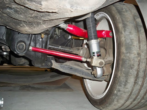
Finally…Droop.
This is a crazy increase compared to last summer.
After opting to go with the S15 diff, I have to keep my rear wheels planted all the time, even more so than before. The diff transfers some large percentage of torque to the wheel with most grip, but if a wheel lifts, (Large %)*(0) = 0 torque at the planted wheel, and all torque at the lifted wheel = open diff. It always has positive effects, except when in the air.
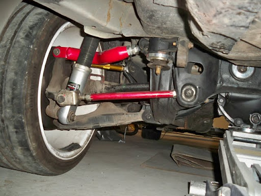
Anyway, this is what my new tenders & such gave me.
Last year.
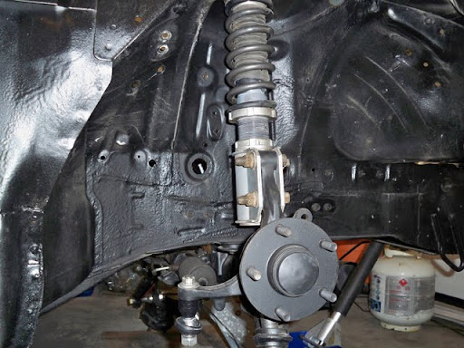
Now!


My fronts won’t be any different.
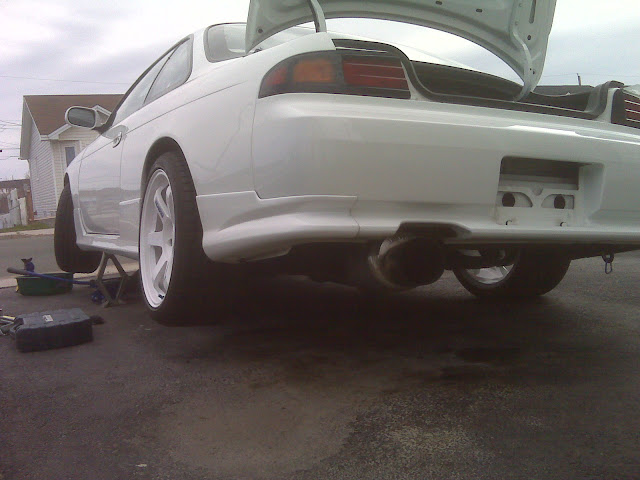
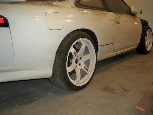
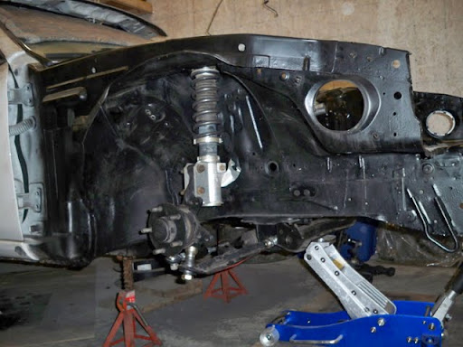
Here is how they look just against the inner fender, without the outer fender.

I’m kind of considering some tenders for the front to avoid this:

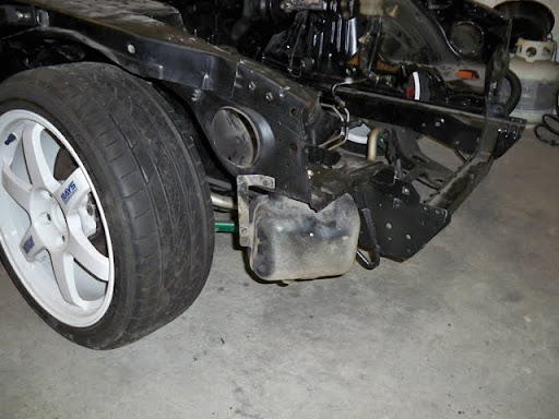
After I bolted the wheels on, took one last pic, then dropped it back onto the floor.

Slammed…lol

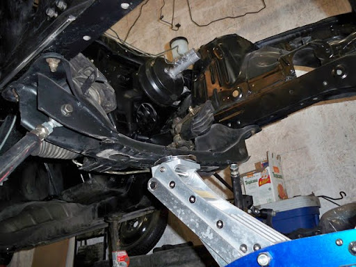
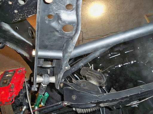
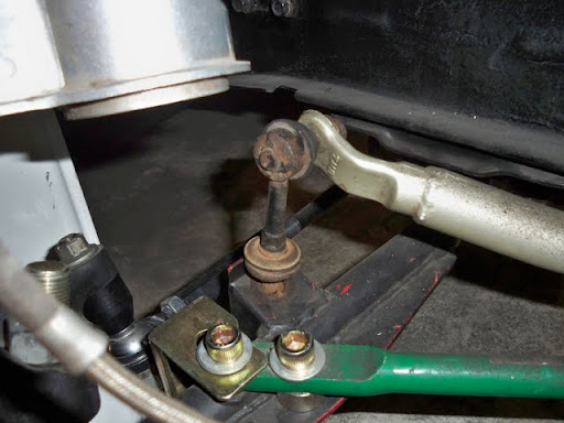
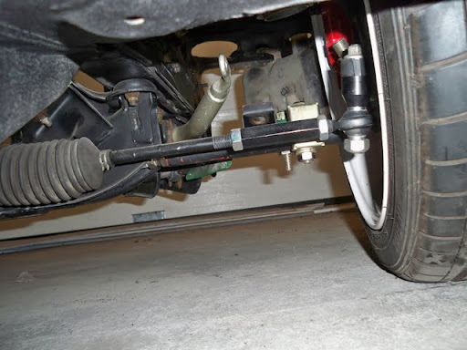
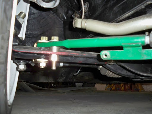
Next on the block was sizing up the differential/handbrake cable clearance.
I got a heads-up from Full Race Geoff, and decided to check into it.
He said that after raising his subframe like I did, he destroyed his aluminum driveshaft this week.
I looked into it, and yeah, some spacing will be in order.
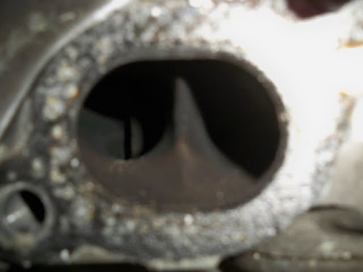
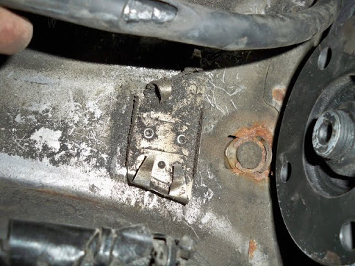
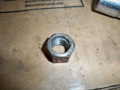
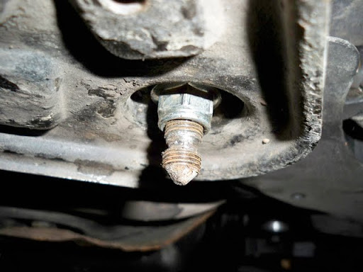
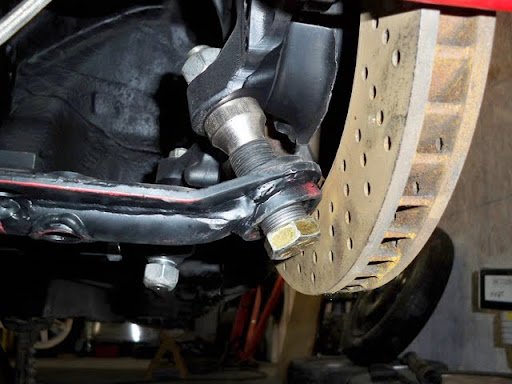
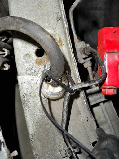
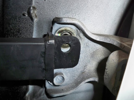
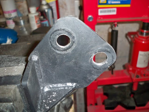
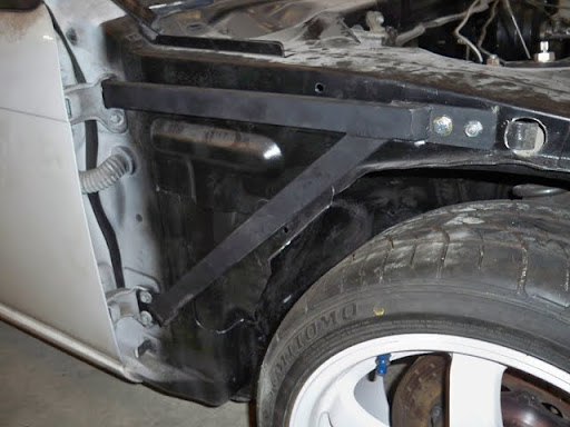
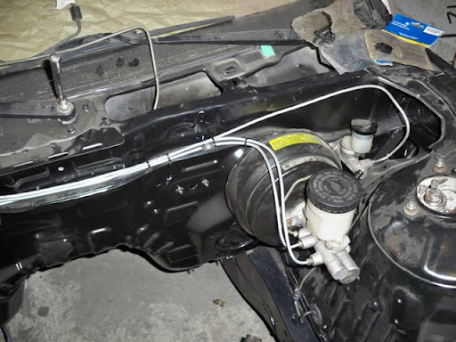
The first pic shows how high the nose of the diff is now, and also shows the visible damage to the cable sleeves from before I bought the car, and some remnants of the zipties I used to tie them up and out of the way last summer.

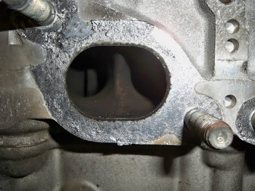
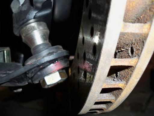
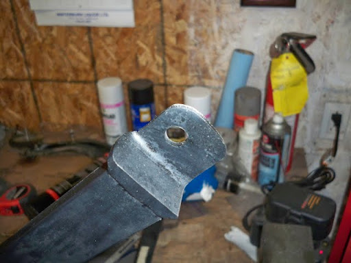
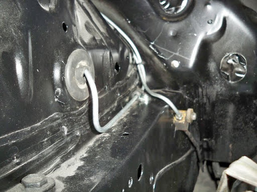
The second pic just gives a different perspective, and still shows how high the flange is.

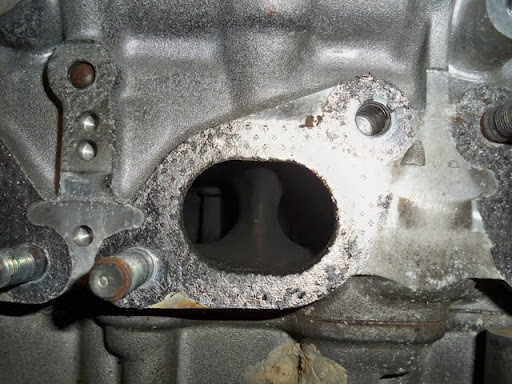
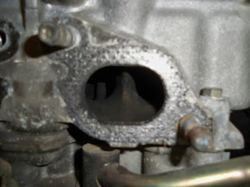
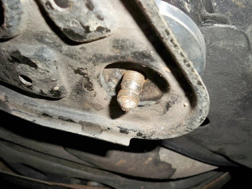
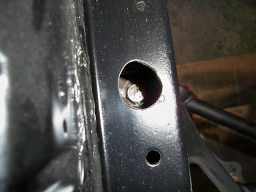
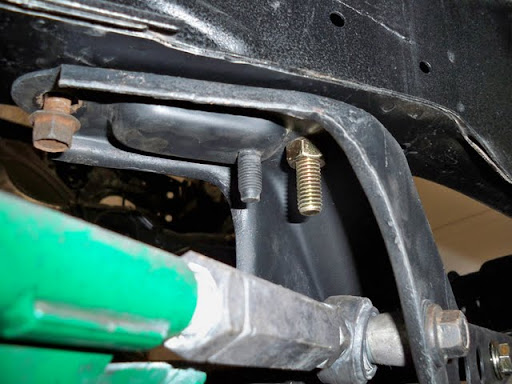
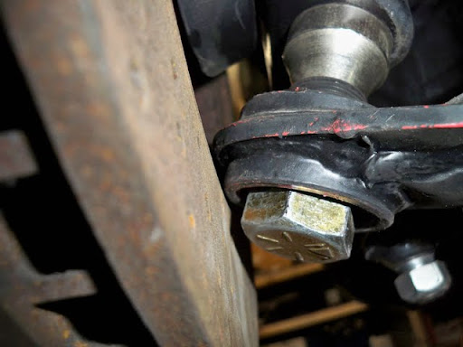
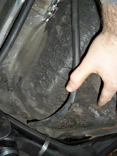
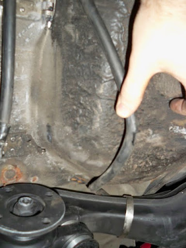
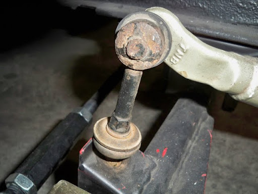
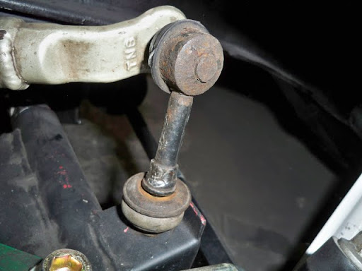
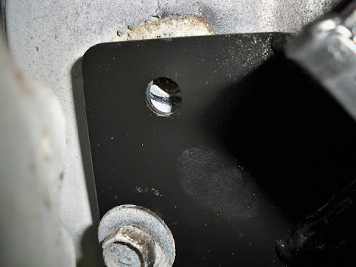
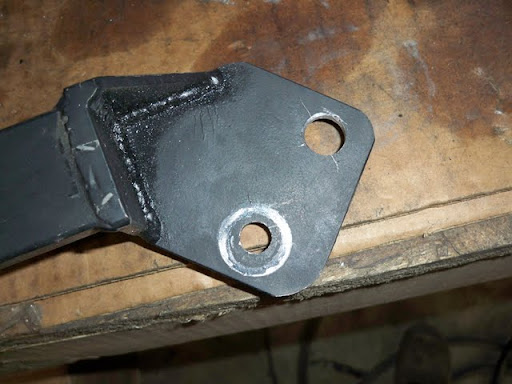
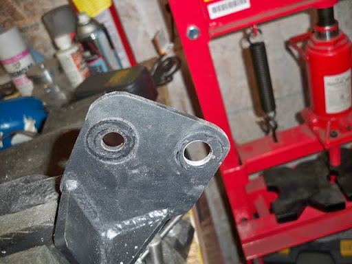
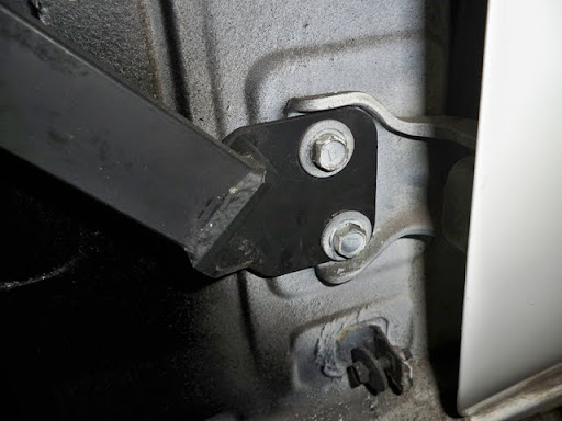
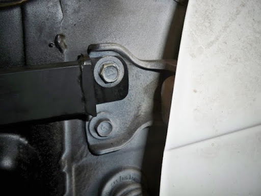
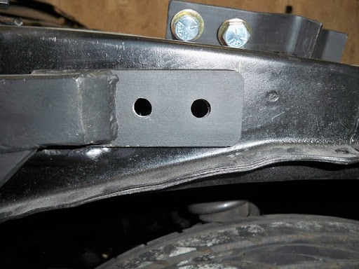
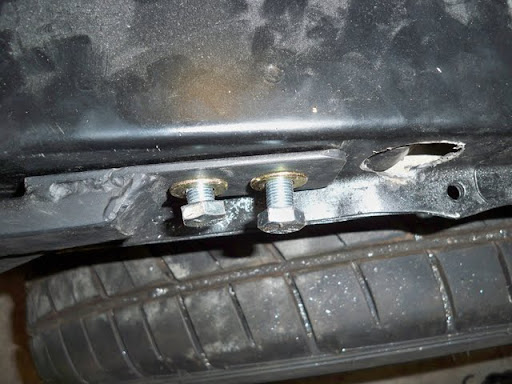
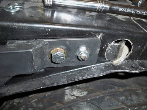
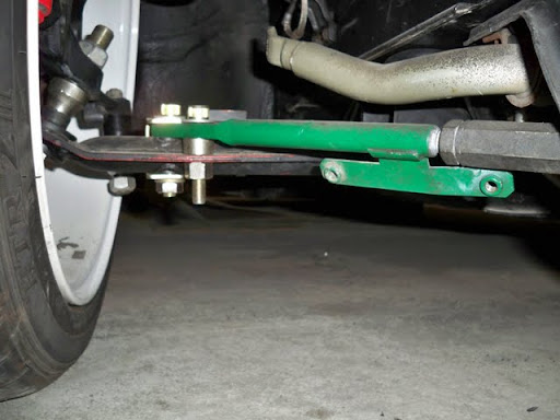
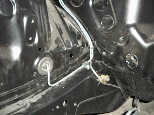
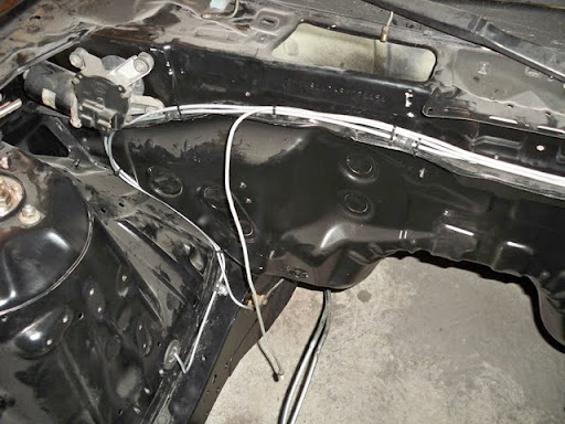
The following 3 pics show the stock (crappy) brackets that hold the cables in place.
The first is fine, 2nd is crap, 3rd is actually destroyed.


I’m actually thinking about using some washers to space the nose down between the top bushing and subframe, and possibly re-routing the cables on the gas tank heat shield as shown (if required).

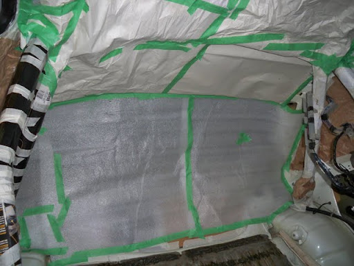
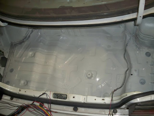
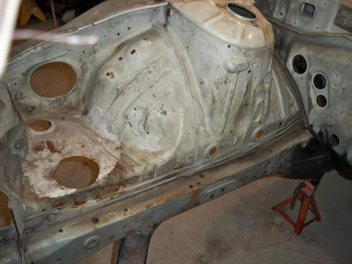
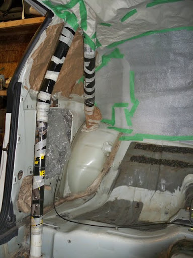
Finally…and this is, I think, the definition of a keeper…Not only did the GF climb onto the top shelf and pass down wheels at the beginning of the night, but also fully masked and painted the interior of the car while I was doing all the other crap.


Then, after I buffed the trunk areas that needed attention, hit the trunk with a coat of paint.


 wish i had a girlfriend that would help me at least hand the tools to me while i work on my 240sx lol